ALSTOM MVAJ105RA0802A Protection Relay – MiCOM Series
ALSTOM MVAJ105RA0802A Protection Relay: Supply Continuity Strategy for a Discontinued Critical Component The ALSTOM MVAJ105RA0802A is a numerical protection relay…
Model: 6716864-2B 556393 DSL-16-25-270-P-A-S20-B 810-800961-009
Product Overview
Commercial availability is handled through direct RFQ, model verification and export-oriented follow-up rather than public cart checkout.
Datasheet Preview
Use attached product manuals when available. If the manual is not public yet, request the full file directly through RFQ.
Commercial Path
Product pages on DRIVEKNMS are designed to verify model, brand and series first, then move the buyer into one clean quotation path.
Technical Dossier
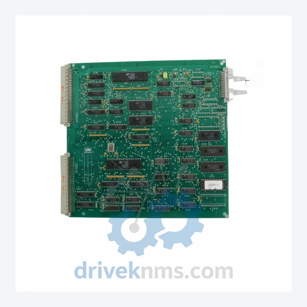
The Merlin Gerin DSL Series represents the electronic control and protection board architecture deployed across Merlin Gerin's (now Schneider Electric) Compact NS, Masterpact, and legacy Multicompact circuit breaker platforms. These PCB assemblies are installed in critical power distribution infrastructure across petrochemical plants, nuclear facilities, offshore platforms, steel mills, and large-scale utility substations worldwide. The DSL control boards govern trip unit logic, earth fault protection, overload detection, and communication interfaces within low-voltage and medium-voltage switchgear panels. Their continued operational relevance in aging industrial facilities makes sourcing of exact-match replacement boards a high-priority maintenance requirement.
Merlin Gerin introduced the DSL electronic trip unit platform in the late 1980s as part of the transition from purely electromechanical protection relays to microprocessor-based protection logic within molded-case and air circuit breakers. Early DSL boards used discrete analog circuitry for current sensing and threshold comparison. By the mid-1990s, the architecture incorporated dedicated ASICs for protection curve computation, enabling IEC 60947-2 compliant time-current characteristic programming (L, S, I, G functions).
The DSL-16 and DSL-25 sub-families introduced modular backplane connectors, allowing field replacement of the control PCB without full breaker disassembly. The suffix notation (e.g., DSL-16-25-270-P-A-S20-B) encodes frame size, rated current range, protection function set, and communication option. The -P suffix denotes a Micrologic-compatible protection profile; -S20 indicates a 20-pin backplane interface standard; -B designates the board revision level.
With Schneider Electric's acquisition of Merlin Gerin in 1992 and full brand consolidation by 2004, the DSL platform was progressively superseded by the Micrologic 2.0, 5.0, 6.0, and 7.0 trip unit families for new installations. However, the DSL boards remain the only compatible replacement for installed Compact NS and legacy Masterpact frames manufactured prior to 2002. No firmware-compatible cross-reference exists between DSL and Micrologic platforms without full trip unit assembly replacement.
PCB Assemblies & Control Boards
The DSL Series entered end-of-production status progressively between 2003 and 2008 as Schneider Electric completed the Micrologic platform rollout. Schneider Electric's official spare parts program no longer stocks the majority of DSL PCB assemblies, with last-time-buy windows having closed for most board variants. This creates a critical sourcing gap for facilities operating Compact NS 100N, 160N, 250N, and legacy Masterpact M frames that cannot be upgraded without full switchgear panel replacement.
DriveKNMS maintains a dedicated inventory of DSL Series PCB assemblies sourced from decommissioned panels, authorized surplus channels, and long-term storage stock. Each unit is catalogued by full part number including revision suffix to ensure exact-match replacement. DriveKNMS provides cross-reference verification against the original breaker frame serial number and manufacture date to confirm board compatibility before shipment. For facilities requiring multiple boards across a site, DriveKNMS offers consolidated procurement with unified quality documentation.
DSL Series PCB assemblies present specific test challenges due to their integrated backplane connector systems, ASIC-based protection logic, and analog current sensing front-ends. DriveKNMS applies the following test protocol to all DSL boards prior to dispatch:
Related Paths
ALSTOM MVAJ105RA0802A Protection Relay: Supply Continuity Strategy for a Discontinued Critical Component The ALSTOM MVAJ105RA0802A is a numerical protection relay…
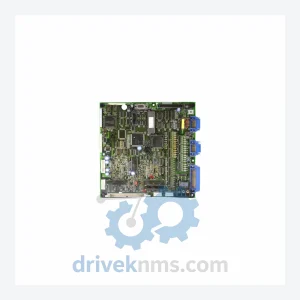
MOORE 16137 Series: Comprehensive Module Range and Technical Overview The MOORE 16137 Series represents a core component family within Moore…
Yaskawa YPHT11014-1A Circuit Board – Obsolete Drive Control Spare Part When a Yaskawa YPHT11014-1A circuit board fails in a production…