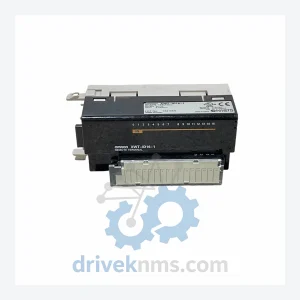
OMRON XWT Series Modules
OMRON XWT Series: Comprehensive Module Range and Technical Overview The OMRON XWT Series represents OMRON's dedicated line of DeviceNet-compatible remote…
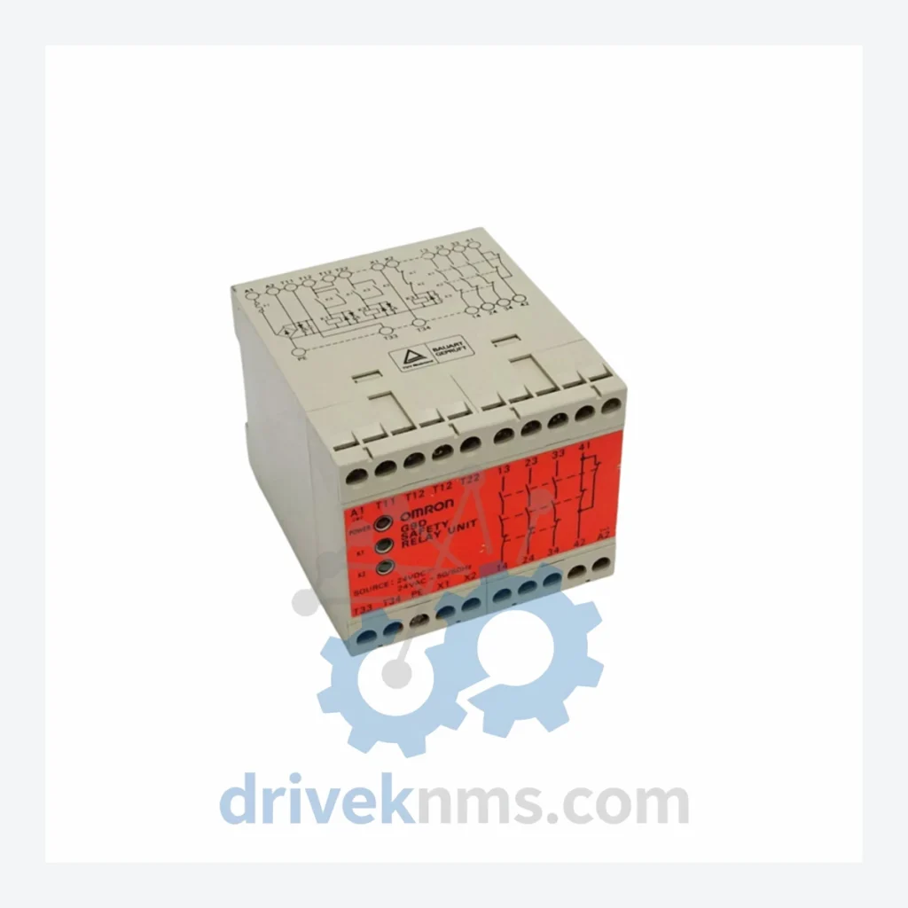
Model: G9D-301
Product Overview
Commercial availability is handled through direct RFQ, model verification and export-oriented follow-up rather than public cart checkout.
Datasheet Preview
Use attached product manuals when available. If the manual is not public yet, request the full file directly through RFQ.
Commercial Path
Product pages on DRIVEKNMS are designed to verify model, brand and series first, then move the buyer into one clean quotation path.
Technical Dossier
The OMRON G9D Series Safety Relay Units are deployed across global heavy industry sectors including chemical processing plants, petroleum refineries, nuclear power facilities, and automotive manufacturing lines. Designed to meet IEC 61508 and ISO 13849 functional safety standards, the G9D Series provides machine safety interlock control, emergency stop (E-Stop) circuit monitoring, and safety gate supervision. These units are certified to Safety Integrity Level (SIL) 3 and Performance Level (PL) e, making them a reference-grade solution for safety-critical control architectures. The G9D-301 in particular is widely installed in legacy safety systems across Asia-Pacific and European industrial facilities, where long-term spare parts availability is a primary operational concern.
The G9D Series was introduced by OMRON as part of its dedicated safety relay product line, succeeding earlier discrete relay-based safety circuits. The architecture is built around a dual-channel redundant input design with cross-fault detection, enabling compliance with Category 4 / PLe per ISO 13849-1. Early variants in the G9D family used DIN-rail mounted relay output blocks with manual or automatic reset options. As industrial safety standards evolved through the 2000s and 2010s, OMRON expanded the G9D range to cover a broader set of input types — including two-hand control, light curtain interfaces, and muting functions — while maintaining backward-compatible wiring footprints where possible. The G9D-301 represents the standard single-function E-Stop / safety gate monitoring variant. Facilities running G9D units installed prior to 2015 should note that some sub-variants have entered the mature/end-of-active-production phase; OMRON continues to provide repair and replacement support, but new production lead times may be extended. DriveKNMS maintains buffer stock of G9D-301 and related models specifically to support lifecycle extension programs for these installations.
The following SKUs represent the verified G9D Series module range. Each unit is classified by primary safety function. Models not belonging to the G9D Series are excluded.
Emergency Stop / Safety Gate Monitoring
Two-Hand Control
Light Curtain / ESPE Interface
Muting Function
Safety Mat / Pressure-Sensitive Device Interface
Enabling Device / Hold-to-Run
Multi-Function / Configurable
DriveKNMS specializes in lifecycle extension support for OMRON G9D Series units that have entered the mature or end-of-active-production phase. For facilities operating safety systems with G9D-301, G9D-302, or G9D-303 units installed prior to 2018, sourcing replacement modules through standard distribution channels may involve extended lead times of 8–20 weeks or result in substitution with non-identical replacement models that require re-validation of the safety function. DriveKNMS maintains independently sourced buffer stock of G9D Series modules, verified against original OMRON part numbers. All units are supplied with full traceability documentation. For end-of-life (EOL) models, DriveKNMS can provide cross-reference analysis to identify functionally equivalent current-production OMRON safety relay alternatives, reducing re-engineering scope for the customer's safety validation team.
Each G9D Series unit processed by DriveKNMS undergoes a structured inspection and functional test protocol prior to dispatch. The test procedure covers: (1) Visual inspection of relay contact condition, terminal block integrity, and housing for mechanical damage or evidence of thermal stress. (2) Dual-channel input simulation — both channels are independently actuated and cross-faulted to verify correct fault detection and output de-energization response. (3) Output contact resistance measurement across all N.O. and N.C. safety contacts using a calibrated milliohm meter. (4) Reset function verification — both manual and automatic reset modes are tested where applicable to the specific model. (5) Power supply range test — units are energized at 85% and 110% of rated supply voltage to confirm stable operation across the specified tolerance band. (6) Response time measurement — output drop-out time is measured and compared against the published datasheet specification. Units that fail any test parameter are quarantined and not supplied. Test records are retained and available upon request for customer safety file documentation.
Related Paths
OMRON XWT Series: Comprehensive Module Range and Technical Overview The OMRON XWT Series represents OMRON's dedicated line of DeviceNet-compatible remote…
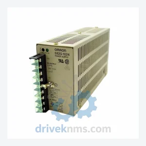
OMRON S82G-1024 Power Supply Unit: Global Sourcing Strategy & Asset Return Value The OMRON S82G-1024 is a proven industrial power…
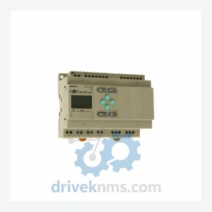
OMRON ZEN-20C1DR-D-V1: Procurement Strategy & Asset Return Value in a Constrained Supply Chain The OMRON ZEN-20C1DR-D-V1 is a compact programmable…