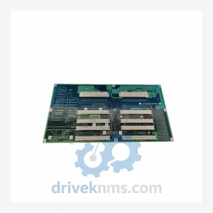
NIKON 4S018-659 Backplane Interface Board – Precision Motion Control
NIKON 4S018-659 Backplane Interface Board: Securing Supply Continuity for Semiconductor & Precision Manufacturing Lines The NIKON 4S018-659 is a backplane…
Model: 4S018-713-1 NSR-S306C
Product Overview
Commercial availability is handled through direct RFQ, model verification and export-oriented follow-up rather than public cart checkout.
Datasheet Preview
Use attached product manuals when available. If the manual is not public yet, request the full file directly through RFQ.
Commercial Path
Product pages on DRIVEKNMS are designed to verify model, brand and series first, then move the buyer into one clean quotation path.
Technical Dossier
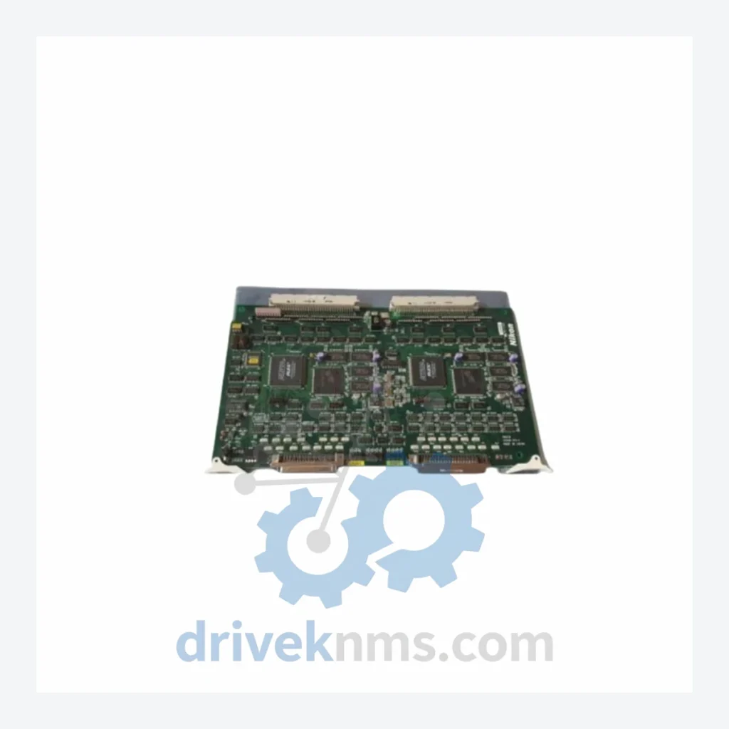
The NIKON NSR-S306C is a deep-ultraviolet (DUV) step-and-repeat lithography system engineered for high-volume semiconductor wafer production. Deployed across semiconductor fabs, flat-panel display manufacturers, and advanced packaging facilities worldwide, the NSR-S306C platform represents a mature generation of NIKON stepper technology operating at 248 nm KrF excimer laser wavelength with a numerical aperture (NA) of 0.63. Its installed base spans facilities in Japan, South Korea, Taiwan, the United States, and Europe, where it continues to serve as a production workhorse for 0.25 µm to 0.35 µm design rule nodes. The system's modular electronics architecture — built around distributed PCB assemblies for stage control, illumination, alignment, and reticle handling — means that circuit board availability is a direct determinant of tool uptime. The 4S018-713-1 circuit board is one such critical sub-assembly within the NSR-S306C control electronics stack.
NIKON's NSR (Nikon Step and Repeat) platform evolved through successive generations from the early 1980s through the 2000s. The NSR-S306C belongs to the KrF (248 nm) generation, succeeding i-line (365 nm) systems such as the NSR-1755i7A and NSR-2205i14E. Within the KrF lineage, the progression ran from the NSR-S202A through the NSR-S204B, NSR-S205C, NSR-S302H, NSR-S305B, NSR-S306C, and ultimately to the NSR-S307E and NSR-S308F before NIKON transitioned its leading-edge roadmap to ArF (193 nm) systems (NSR-S609B, NSR-S620D) and immersion platforms (NSR-S621D, NSR-S631D).
The NSR-S306C introduced enhanced stage interferometry, improved reticle alignment algorithms, and a revised illumination uniformity control system compared to its predecessor the NSR-S305B. Its control electronics are distributed across multiple PCB assemblies communicating over proprietary NIKON backplane buses. As the NSR-S306C has entered the mature/end-of-life phase of its product lifecycle, OEM spare parts supply has been discontinued or severely constrained. Facilities maintaining these tools must rely on third-party spare parts distributors for circuit board replacements, repair, and long-term maintenance support. Compatibility between NSR-S306C boards and adjacent series (NSR-S305B, NSR-S307E) is partial and must be verified by part number before substitution.
The following SKUs represent verified circuit board and module part numbers associated with the NIKON NSR-S306C platform. Each entry reflects a discrete functional sub-assembly within the system's control, motion, illumination, or alignment architecture.
4S018-713-1: NSR-S306C main control circuit board sub-assembly, distributed control bus interface.
4S018-714-1: Stage X-axis servo drive control PCB, interferometer signal processing.
4S018-715-1: Stage Y-axis servo drive control PCB, closed-loop position feedback.
4S018-716-1: Z-axis focus and leveling control board, autofocus servo interface.
4S018-720-1: Reticle stage control PCB, reticle alignment and scan synchronization.
4S018-721-1: Illumination control board, KrF excimer laser energy dose regulation.
4S018-722-1: Alignment sensor signal processing PCB, wafer mark detection interface.
4S018-730-1: Wafer handler interface board, EFEM and robot arm communication.
4S018-731-1: Environmental control PCB, temperature and humidity sensor integration.
4S018-740-1: Main CPU board, system sequencer and recipe management processor.
4S018-741-1: I/O expansion board, digital input/output signal distribution.
4S018-742-1: Communication adapter PCB, host computer and CIM interface (SECS/GEM).
4S018-750-1: Power supply regulation board, DC bus conditioning and fault detection.
4S018-751-1: Interlock and safety relay PCB, emergency stop and door interlock logic.
4S018-760-1: Lens aberration correction control board, optical element actuator interface.
4S018-761-1: Shutter and aperture control PCB, illumination field stop actuation.
4S018-770-1: Diagnostic and logging board, real-time error capture and data storage.
The NIKON NSR-S306C has been out of OEM production support for over a decade. NIKON Precision no longer manufactures or distributes replacement circuit boards for this platform through standard channels. Semiconductor fabs and equipment maintenance teams operating NSR-S306C tools face a constrained supply environment where original boards must be sourced from decommissioned systems, third-party refurbishers, or specialist distributors.
Circuit boards recovered from decommissioned NSR-S306C systems undergo a structured inspection and functional verification process before being offered for sale. The NSR-S306C's backplane bus architecture requires that boards be tested both in isolation and in the context of their bus communication behavior, as passive visual inspection alone is insufficient to confirm functional integrity.
DriveKNMS applies the following verification steps to NSR-S306C boards: visual inspection for physical damage, corrosion, and component-level defects; in-circuit testing (ICT) of passive and active components; functional power-on testing under controlled DC supply conditions; bus communication verification where applicable; and burn-in cycling to screen for latent failures. Boards that do not pass all stages are either routed for component-level repair or classified as non-functional and excluded from inventory. Each board shipped is accompanied by a test record and condition report.
© 2026 DriveKNMS.
Related Paths
NIKON 4S018-659 Backplane Interface Board: Securing Supply Continuity for Semiconductor & Precision Manufacturing Lines The NIKON 4S018-659 is a backplane…

NIKON C304 Series: Comprehensive Module Range and Technical Overview The NIKON C304 series PCB cards are precision control boards deployed…
NIKON GLG5412 Power Module: Global Sourcing Strategy & Asset Return Value The NIKON GLG5412 is a precision laser power module…