
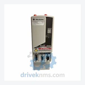
Allen-Bradley 2094-BC01-M01-S Integrated Axis Module – Kinetix 6000
Allen-Bradley 2094-BC01-M01-S is listed for Kinetix 6000 RFQ review. Confirm quantity, condition and destination before quotation.
RFQ-ready industrial model
Model: 2094-BC07-M05-S SER C
Product Overview
Commercial availability is handled through direct RFQ, model verification and export-oriented follow-up rather than public cart checkout.
Datasheet Preview
Use attached product manuals when available. If the manual is not public yet, request the full file directly through RFQ.
Commercial Path
Product pages on DRIVEKNMS are designed to verify model, brand and series first, then move the buyer into one clean quotation path.
Technical Dossier
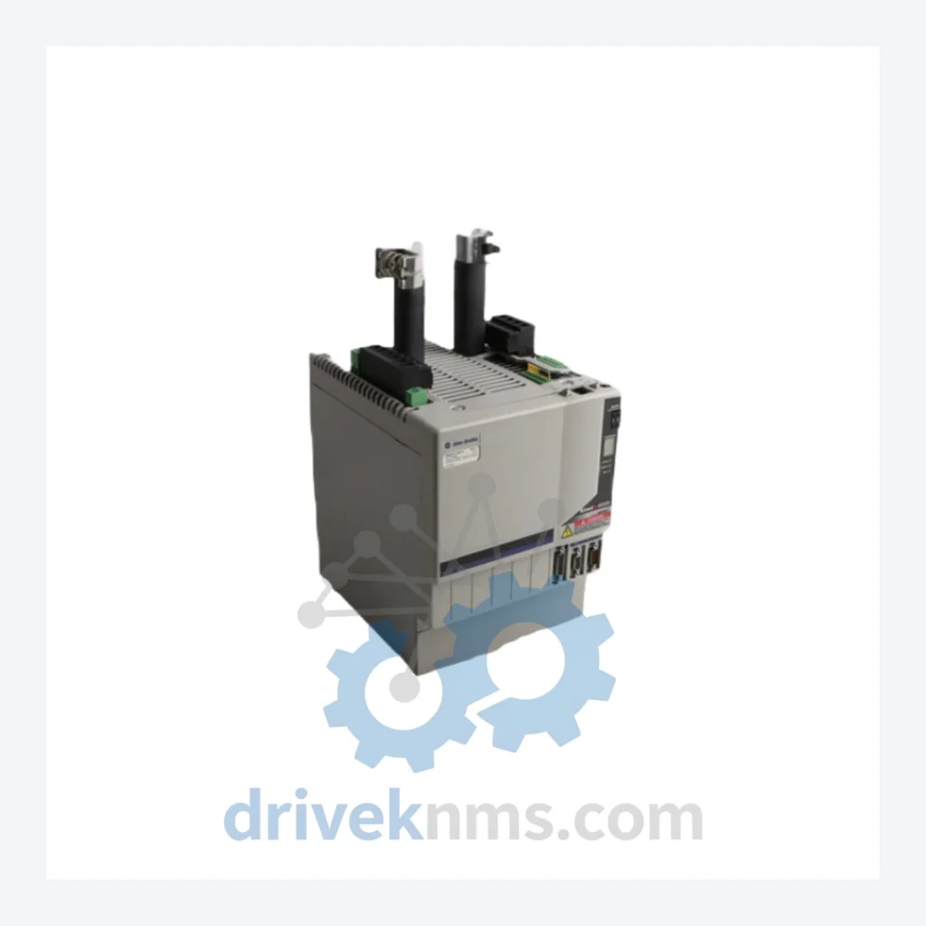
The Allen-Bradley Kinetix 6000 multi-axis servo drive system is a Rockwell Automation platform deployed across heavy industrial sectors including petrochemical refining, nuclear power auxiliary systems, automotive body-in-white lines, and continuous-process paper mills. Its integrated axis module (IAM) and axis module (AM) architecture allows multiple axes to share a common DC bus, reducing cabinet footprint and simplifying power distribution. The 2094-BC07-M05-S SER C is a dual-axis integrated axis module rated at 7 A continuous / 21 A peak on the converter axis and 5 A continuous / 15 A peak on the inverter axis, designed for 400–480 VAC three-phase input. Series C denotes the third hardware revision, incorporating updated IGBT gate driver circuitry and improved thermal management over Series A and B predecessors.
Kinetix 6000 installations are found in facilities where axis counts range from 2 to 16 per power rail, coordinated through a Logix-family controller via SERCOS II fiber-optic ring. The platform's deterministic motion control capability — with 1 ms update rates — makes it a reference design for synchronized multi-axis applications such as flying shear, winding, and pick-and-place.
The Kinetix 6000 platform was introduced in the early 2000s as Rockwell Automation's answer to the demand for a shared-bus, multi-axis servo architecture compatible with the ControlLogix and CompactLogix ecosystems. The original Series A modules used SERCOS I communication and supported a limited range of power ratings. Series B introduced expanded current ratings, improved EMC filtering, and compatibility with the 2090-series feedback cables. Series C — the current production revision for most catalog numbers — added enhanced diagnostic LEDs, revised firmware for axis-level fault isolation, and updated capacitor specifications for extended service life in high-ambient-temperature environments.
The Kinetix 6000 operates on the 2094 power rail system. The power rail (e.g., 2094-PRF) provides the mechanical and electrical backbone for mounting IAMs and AMs side by side. Communication between the controller and drives uses a SERCOS II ring at 4 or 8 Mbit/s over fiber-optic cable. As of 2020, Rockwell Automation has designated the Kinetix 6000 as a mature product, with the Kinetix 5700 (2198 series) positioned as the recommended migration path for new designs. However, the installed base of Kinetix 6000 systems in operating plants remains substantial, and spare parts demand continues through the 2030s based on typical plant lifecycle planning.
Integrated Axis Modules (IAM) — Converter + Inverter combined:
Axis Modules (AM) — Inverter only, shared DC bus:
Power Rails & Infrastructure:
Communication & Feedback Accessories:
Kinetix 6000 modules present specific test challenges due to their integrated converter-inverter topology and SERCOS II communication dependency. DriveKNMS applies the following test protocol to all 2094-series units prior to shipment:
Continue The Model Path
Move from this exact model into the matching system hub, brand archive, model-family archive or lifecycle sourcing route before sending a final RFQ list.
Related Paths
Allen-Bradley 2094-BC01-M01-S is listed for Kinetix 6000 RFQ review. Confirm quantity, condition and destination before quotation.
Allen-Bradley 2094-PRS8 is listed for Kinetix 6000 RFQ review. Confirm quantity, condition and destination before quotation.
Allen-Bradley 2094-BC02-M02-S is listed for Kinetix 6000 RFQ review. Confirm quantity, condition and destination before quotation.