
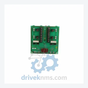
ABB NTCL01 Communication Termination Unit
ABB NTCL01 is listed for Communication Modules RFQ review. Confirm quantity, condition and destination before quotation.
RFQ-ready industrial model
Model: 560CMU05 1KGT012700R0002
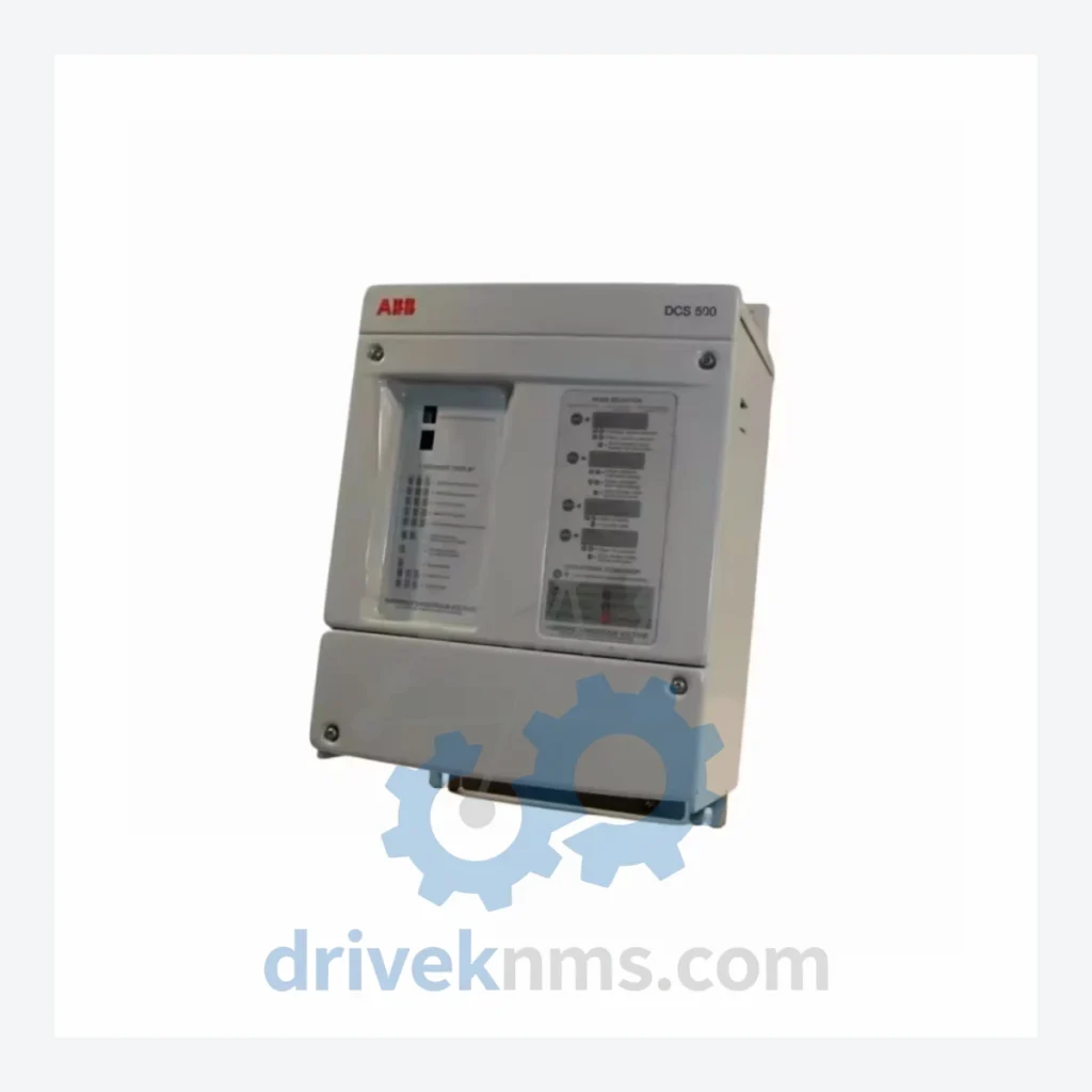
Product Overview
Commercial availability is handled through direct RFQ, model verification and export-oriented follow-up rather than public cart checkout.
Datasheet Preview
Use attached product manuals when available. If the manual is not public yet, request the full file directly through RFQ.
Commercial Path
Product pages on DRIVEKNMS are designed to verify model, brand and series first, then move the buyer into one clean quotation path.
Technical Dossier
The AC500 platform was introduced by ABB in the early 2000s as a successor to the legacy Advant and Masterpiece controller families. The first generation (AC500 V1) established the modular CPU + I/O bus concept using the S500 I/O system over a proprietary backplane. The second generation introduced the PM5xx CPU family with expanded memory, onboard Ethernet, and PROFIBUS DP master/slave capability. The current generation (AC500 V3 / PM5000 series) integrates multi-core processing, OPC UA server, PROFINET IRT, EtherNet/IP, and IEC 62443 cybersecurity compliance. Communication modules such as the 560CMU05 (1KGT012700R0002) bridge legacy fieldbus infrastructure to modern Ethernet-based supervisory systems, providing backward compatibility for installed AC500 V1/V2 nodes. Compatibility constraints exist between V1 and V3 CPUs regarding I/O bus voltage levels and firmware versioning — cross-generation module substitution requires engineering validation.
CPU Modules
Communication Modules
Digital Input Modules
Digital Output Modules
Analog Input Modules
Power Supply Modules
AC500 communication modules including the 560CMU05 (1KGT012700R0002) undergo a structured multi-stage verification process at DriveKNMS. Stage 1: Visual and mechanical inspection — connector pin integrity, PCB surface condition, housing latch function, and label authenticity verification against ABB part number databases. Stage 2: Powered functional test — module is installed in an AC500 V2 test rack with a PM564 CPU running a standardized diagnostic program; communication bus initialization, LED status sequence, and firmware version readback are logged. Stage 3: Fieldbus protocol validation — for communication modules, active PROFIBUS DP or Modbus RTU traffic is generated and frame integrity is verified using protocol analyzers. Stage 4: Thermal soak — modules are operated at 55°C ambient for 4 hours to screen latent component failures. All test results are recorded and accompany the shipment as a quality data package.
Continue The Model Path
Move from this exact model into the matching system hub, brand archive, model-family archive or lifecycle sourcing route before sending a final RFQ list.
Related Paths
ABB NTCL01 is listed for Communication Modules RFQ review. Confirm quantity, condition and destination before quotation.
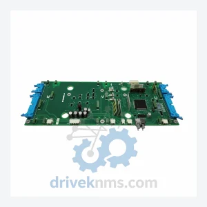
ABB NINT-73C is listed for Communication Modules RFQ review. Confirm quantity, condition and destination before quotation.
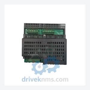
ABB SDCS-IOB-1 3BSE004084R1 is listed for Communication Modules RFQ review. Confirm quantity, condition and destination before quotation.