
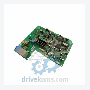
ABB SNAT-7120 Circuit Board – SNAZ7120J Series
ABB SNAT-7120 SNAZ 7120 J SNAZ7120J is listed for SNAZ7120J Series RFQ review. Confirm quantity, condition and destination before quotation.
RFQ-ready industrial model
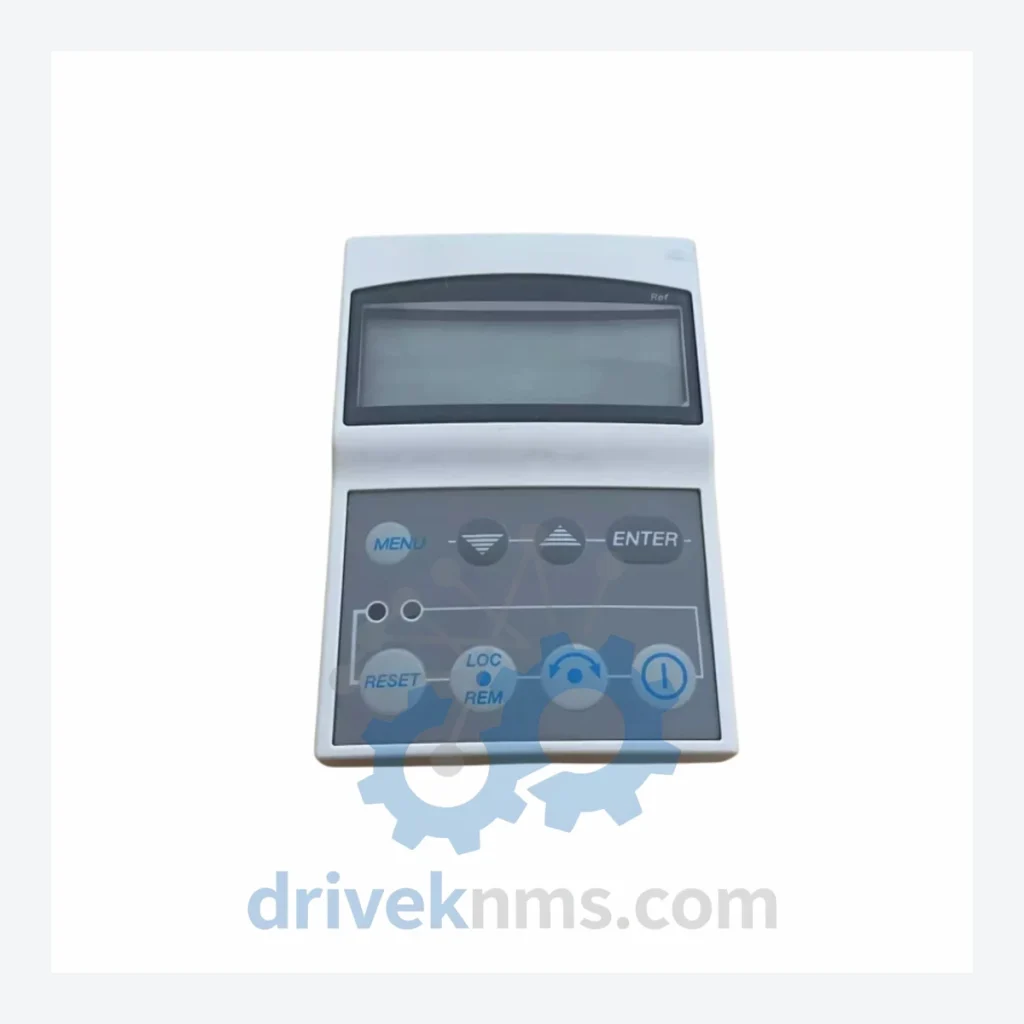
Model: DCS400-PAN-A
Product Overview
Commercial availability is handled through direct RFQ, model verification and export-oriented follow-up rather than public cart checkout.
Datasheet Preview
Use attached product manuals when available. If the manual is not public yet, request the full file directly through RFQ.
Commercial Path
Product pages on DRIVEKNMS are designed to verify model, brand and series first, then move the buyer into one clean quotation path.
Technical Dossier
The DCS400 was introduced by ABB as a rationalized replacement for the DCS300 and earlier Stromberg DC drive families. Its control architecture is based on a dedicated SDCS-CON-2 or SDCS-CON-3 control board, which handles speed and current regulation via a 16-bit microprocessor. The drive communicates with external systems through optional fieldbus adapter modules (SDCS-COM-x series) supporting PROFIBUS-DP, DeviceNet, Modbus RTU, and CANopen protocols.
Early DCS400 units (pre-2003) used the SDCS-CON-2 control board with firmware versions below 10.x. These units are incompatible with SDCS-COM-8 (PROFIBUS) adapters designed for SDCS-CON-3 boards without a control board upgrade. Post-2004 production units standardized on SDCS-CON-3, which introduced expanded parameter memory, improved autotune algorithms, and compatibility with the full SDCS-COM adapter range. The DCS400-PAN-A operator panel is compatible with both SDCS-CON-2 and SDCS-CON-3 control boards, providing a consistent HMI interface across the production lifecycle.
The DCS880 (introduced circa 2015) replaced the DCS400 with a 32-bit ARM-based control platform, Ethernet/IP and PROFINET support, and a unified parameter structure shared with the ACS880 AC drive family. DCS400 spare parts remain available through specialist distributors; ABB's own spare parts support for the DCS400 has transitioned to extended lifecycle status.
The following SKUs represent verified components within the ABB DCS400 ecosystem, classified by functional category:
Operator Panels & HMI
Control Boards
Power Interface & Gate Driver Boards
I/O Expansion Modules
Fieldbus Communication Adapters
Encoder & Feedback Modules
Brake Chopper & Auxiliary
DCS400 modules present specific test challenges due to their integrated backplane bus architecture and the interdependency between the CON board, PIN board, and power stack. DriveKNMS applies the following test protocol to all DCS400 spare parts prior to dispatch:
Continue The Model Path
Move from this exact model into the matching system hub, brand archive, model-family archive or lifecycle sourcing route before sending a final RFQ list.
Related Paths
ABB SNAT-7120 SNAZ 7120 J SNAZ7120J is listed for SNAZ7120J Series RFQ review. Confirm quantity, condition and destination before quotation.
ABB PM564-TP-ETH 1SAP121100R0071 is listed for Servo Drives RFQ review. Confirm quantity, condition and destination before quotation.
ABB SCDCS-CON-4 is listed for CON-4 Control Board RFQ review. Confirm quantity, condition and destination before quotation.