
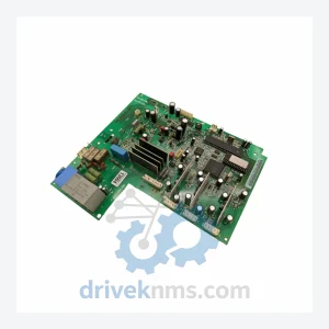
ABB SNAT-7120 Circuit Board – SNAZ7120J Series
ABB SNAT-7120 SNAZ 7120 J SNAZ7120J is listed for SNAZ7120J Series RFQ review. Confirm quantity, condition and destination before quotation.
RFQ-ready industrial model
Model: DSQC345B 3HAB8101-2/07A DSQC346C 3HAB8101-7/10A
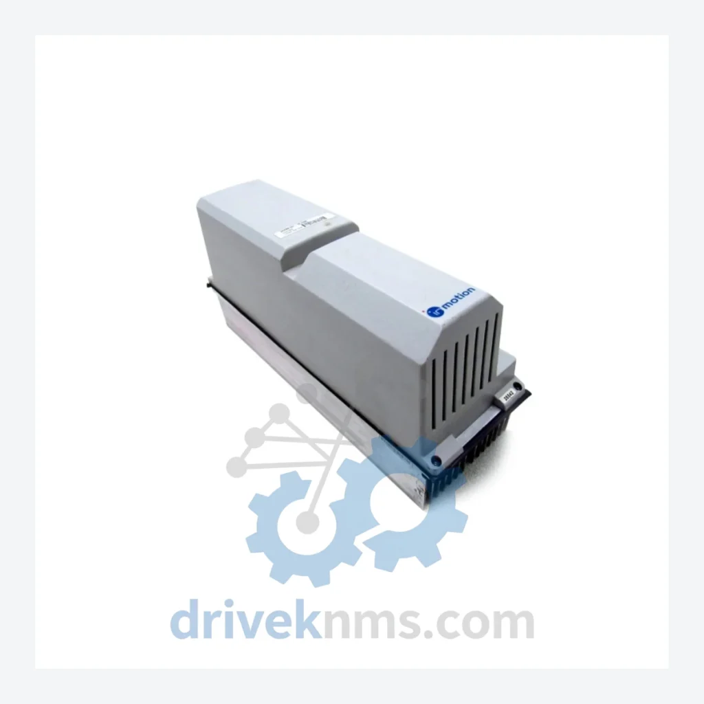
Product Overview
Commercial availability is handled through direct RFQ, model verification and export-oriented follow-up rather than public cart checkout.
Datasheet Preview
Use attached product manuals when available. If the manual is not public yet, request the full file directly through RFQ.
Commercial Path
Product pages on DRIVEKNMS are designed to verify model, brand and series first, then move the buyer into one clean quotation path.
Technical Dossier
ABB's DSQC series spans more than three decades of robot controller development, tracking the evolution from the S3 controller (early 1980s) through S4, S4C, S4C+, and into the IRC5 platform introduced in 2004. Each controller generation introduced a new backplane bus standard and revised the DSQC module numbering scheme accordingly.
The S3 era (circa 1982–1992) used discrete analog servo boards with limited diagnostics. The S4 era (1992–2000) introduced the DSQC300-series boards — digital axis computers, I/O units, and fieldbus adapters — running on a proprietary VME-derived backplane. The S4C and S4C+ era (1998–2008) extended the DSQC300 and DSQC400 series with enhanced memory, DeviceNet and Profibus communication options, and improved axis synchronization. The IRC5 era (2004–present) migrated to the DSQC600 and DSQC800 series on a new drive module architecture, though many S4C+ installations remain in active production globally.
The DSQC345B and DSQC346C belong to the S4/S4C+ generation. These boards are no longer manufactured by ABB and are not available through standard distribution channels. Facilities still operating S4C+ controllers must source these modules from specialist aftermarket suppliers. Migrating an S4C+ robot to IRC5 requires mechanical recabling, software re-commissioning, and in many cases new end-of-arm tooling interfaces — a project cost that typically ranges from USD 40,000 to USD 120,000 per robot. Against that figure, sourcing a verified DSQC345B or DSQC346C from aftermarket inventory is the operationally rational decision.
The following models represent confirmed members of the ABB DSQC series across S4, S4C, and S4C+ controller generations. Each entry reflects a distinct hardware function within the robot controller rack.
Axis Computer / CPU Modules
Drive / Servo Amplifier Modules
I/O Modules
Communication / Fieldbus Adapter Modules
Power Supply Modules
DSQC drive and axis boards present specific failure modes that require targeted inspection protocols. DriveKNMS applies the following test sequence to all DSQC units prior to dispatch:
Continue The Model Path
Move from this exact model into the matching system hub, brand archive, model-family archive or lifecycle sourcing route before sending a final RFQ list.
Related Paths
ABB SNAT-7120 SNAZ 7120 J SNAZ7120J is listed for SNAZ7120J Series RFQ review. Confirm quantity, condition and destination before quotation.
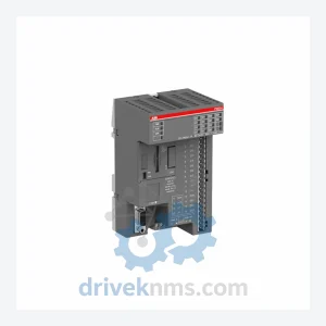
ABB PM564-TP-ETH 1SAP121100R0071 is listed for Servo Drives RFQ review. Confirm quantity, condition and destination before quotation.
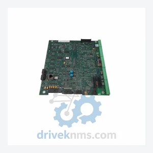
ABB SCDCS-CON-4 is listed for CON-4 Control Board RFQ review. Confirm quantity, condition and destination before quotation.