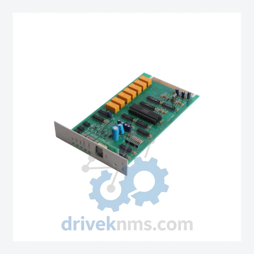
ABB SLC Modules: EM-CAY

Model: EM-CAY

Brand ABB
Series SLC
Model EM-CAY
RFQ-ready model route Obsolete and surplus sourcing Export follow-up by model list

Product Overview

Commercial availability is handled through direct RFQ, model verification and export-oriented follow-up rather than public cart checkout.

Datasheet Preview

Datasheet Preview

Use attached product manuals when available. If the manual is not public yet, request the full file directly through RFQ.

Request Full Manual

Commercial Path

Use This Page To Confirm The Model, Then Move To RFQ

Product pages on DRIVEKNMS are designed to verify model, brand and series first, then move the buyer into one clean quotation path.

Technical Dossier

Product Details And Specifications

ABB SLC Series Technical Notes

The Evolution of SLC Architecture

The SLC platform was introduced in the late 1980s as part of ABB's Advant OCS (Open Control System) strategy, designed to bridge the gap between standalone PLCs and full-scale DCS installations. Early SLC hardware operated on proprietary ABB MasterBus 300 and RCOM communication backplanes, with CPU modules executing ABB's AMPL (Advant Master Programming Language) and later IEC 61131-3 structured text. The first-generation SLC rack systems used parallel backplane addressing with fixed slot assignments, limiting scalability but ensuring deterministic scan times below 10 ms for typical I/O configurations.

SLC Full Catalog & Functionalities (SKU List)

CPU & Cross-CPU Modules

  • EM-CAY: Cross-CPU communication module; synchronizes dual-CPU configurations via SLC backplane for hot-standby redundancy.
  • PM-CAY: Primary CPU module for SLC rack; executes AMPL/IEC 61131-3 control programs with 512 KB user memory.
  • PM-CAZ: Enhanced CPU variant with expanded 1 MB program memory and faster scan cycle; direct replacement path for PM-CAY in most configurations.
  • PM-CAX: Entry-level SLC CPU; single-CPU rack configurations without redundancy support.
  • EM-CAX: Cross-CPU interface for PM-CAX-based racks; limited to non-redundant data exchange.

Digital Input (DI) Modules

  • DI-CAY: 16-channel 24 VDC digital input module; IEC 61131-2 Type 1 compliant; 3 ms input filter.
  • DI-CAZ: 32-channel 24 VDC digital input; high-density I/O expansion for large discrete process sections.
  • DI-CAX: 16-channel 120 VAC digital input; used in legacy panel interfaces with AC field wiring.
  • DI-CBY: 16-channel isolated digital input; individual channel isolation for high-noise environments such as motor control centers.

Digital Output (DO) Modules

  • DO-CAY: 16-channel 24 VDC digital output; 0.5 A per channel; short-circuit protected.
  • DO-CAZ: 32-channel 24 VDC digital output; high-density discrete control for valve actuator arrays.
  • DO-CAX: 8-channel relay output module; 250 VAC/30 VDC, 5 A per channel; used for motor starter and contactor interfaces.

Analog Input (AI) Modules

  • AI-CAY: 8-channel analog input; 4–20 mA / 0–10 V selectable; 12-bit resolution; HART pass-through on select firmware versions.
  • AI-CAZ: 16-channel analog input; multiplexed architecture; 13-bit effective resolution; used in temperature and pressure transmitter loops.
  • AI-CBY: 8-channel thermocouple/RTD input; supports J, K, T, E type TC and Pt100/Pt1000 RTD; cold junction compensation onboard.

Analog Output (AO) Modules

  • AO-CAY: 4-channel analog output; 4–20 mA; 12-bit resolution; used for control valve positioner interfaces.
  • AO-CAZ: 8-channel analog output; expanded channel count for multi-loop control sections.

Communication & Fieldbus Adapters

  • CI-CAY: AF 100 (Advant Fieldbus 100) communication interface; connects SLC rack to ABB Advant fieldbus segment.
  • CI-CAZ: PROFIBUS-DP master/slave adapter for SLC; enables integration with third-party field devices and remote I/O stations.
  • CI-CBY: Modbus RTU/TCP gateway module; provides legacy serial communication to SCADA and historian systems.

Power Supply Modules

  • PS-CAY: 24 VDC rack power supply; 10 A output; redundant pair configuration supported.
  • PS-CAZ: 24 VDC redundant power supply module; hot-swap capable; used in high-availability SLC rack builds.

Quality Control for the SLC Range

ABB SLC modules present specific quality control challenges due to their backplane-dependent communication architecture and age-related component degradation. DriveKNMS applies a multi-stage test protocol to all SLC modules prior to dispatch:

  • Visual and mechanical inspection: PCB examination for corrosion, capacitor bulge, connector pin damage, and conformal coating integrity.
  • Power-on functional test: Module is installed in a reference SLC rack running a known-good firmware baseline. Power consumption and initialization sequence are verified against factory specifications.
  • Backplane communication verification: For cross-CPU modules (EM-CAY, EM-CAX), inter-processor data exchange is validated using a dual-CPU test rack with live process simulation. Synchronization latency is measured and compared against ABB's published specification of <2 ms cross-CPU update cycle.
  • I/O channel-level testing: All analog and digital I/O modules are tested channel-by-channel using calibrated signal sources and loads. Analog modules are verified for linearity, offset, and gain accuracy across the full input/output range.
  • Communication adapter validation: Fieldbus and serial communication modules are tested for protocol compliance using network analyzers and reference master/slave configurations.
  • Burn-in and thermal cycling: Selected modules undergo 48-hour burn-in at elevated ambient temperature to screen for early-life failures in aged components.

Continue The Model Path

Use system, brand and series routes to compare related published models.

Move from this exact model into the matching system hub, brand archive, model-family archive or lifecycle sourcing route before sending a final RFQ list.

WhatsApp Prefilled Inquiry Email sale@driveknms.com Phone +86 18359293191 Top Back To Top