
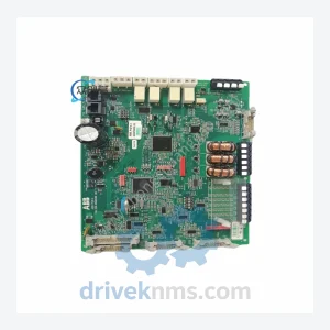
ABB ZPOW Series Power Modules ZPOW-7B1C
ABB ZPOW-7B1C is listed for ZPOW Series Power RFQ review. Confirm quantity, condition and destination before quotation.
RFQ-ready industrial model
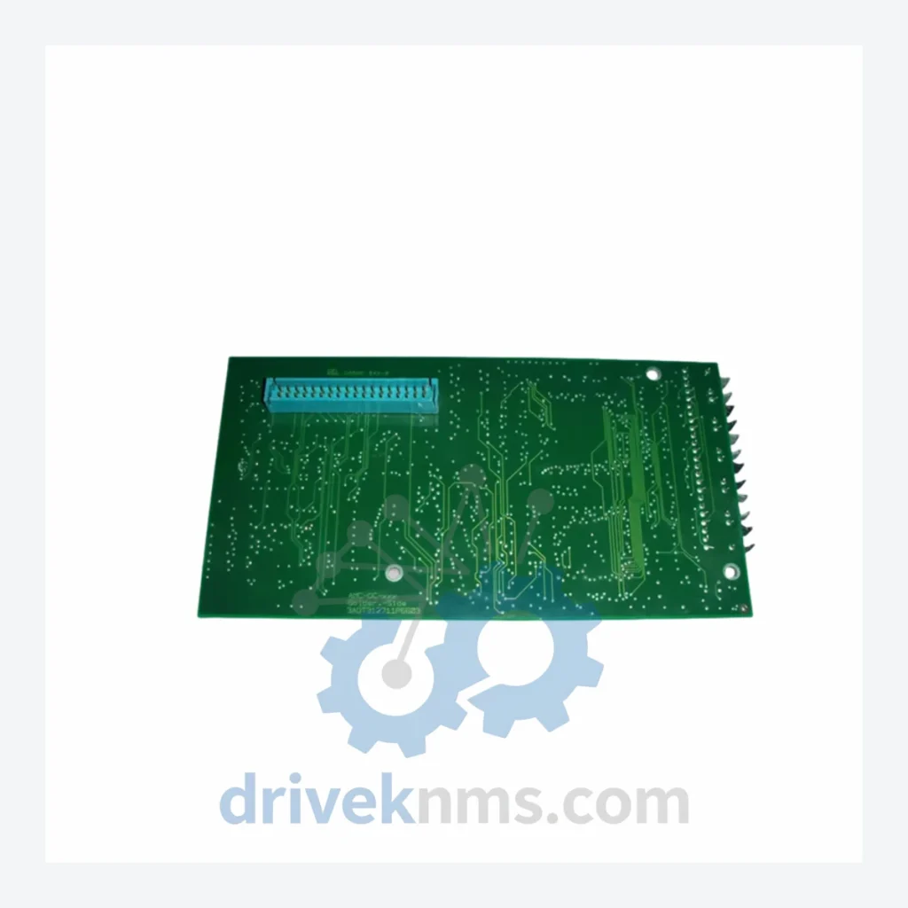
Model: SDCS-AMC-DC-2
Product Overview
Commercial availability is handled through direct RFQ, model verification and export-oriented follow-up rather than public cart checkout.
Datasheet Preview
Use attached product manuals when available. If the manual is not public yet, request the full file directly through RFQ.
Commercial Path
Product pages on DRIVEKNMS are designed to verify model, brand and series first, then move the buyer into one clean quotation path.
Technical Dossier
The SDCS platform was introduced alongside the DCS500 series in the early 1990s as a modular replacement for monolithic analog control boards. The first-generation SDCS-CON-1 and SDCS-CON-2 boards established the dual-microprocessor architecture that separates current regulation from speed/torque outer-loop control. With the DCS600 MultiDrive platform, ABB introduced the SDCS-COM series of fieldbus adapters, enabling PROFIBUS-DP and DeviceNet integration without hardware redesign of the base control board.
The DCS800 generation (introduced circa 2003) retained backward-compatible SDCS module slots while upgrading the AMC (Advanced Motor Control) board to 32-bit processing — the SDCS-AMC-DC-2 being the definitive production variant of this generation. The SDCS-PIN-51 and SDCS-PIN-205 power interface boards were redesigned for higher current ratings. By 2015, the DCS800 entered its mature/sustaining phase; ABB's DCT880 successor uses a different control architecture. Plants running DCS800 drives must therefore maintain SDCS spare parts inventories independently, as new production of many SDCS variants has ceased.
The following SKUs represent the verified SDCS module range across DCS500, DCS600, and DCS800 platforms. Each entry reflects a distinct hardware function within the drive control architecture.
AMC / Main Control Boards
Power Interface Boards
I/O Expansion Modules
Communication Adapter Boards
Feedback & Measurement Boards
SDCS modules present specific test challenges due to their multi-layer PCB construction, high-density SMD components, and backplane bus communication protocols. DriveKNMS applies the following test protocol to all SDCS units prior to dispatch:
Continue The Model Path
Move from this exact model into the matching system hub, brand archive, model-family archive or lifecycle sourcing route before sending a final RFQ list.
Related Paths
ABB ZPOW-7B1C is listed for ZPOW Series Power RFQ review. Confirm quantity, condition and destination before quotation.
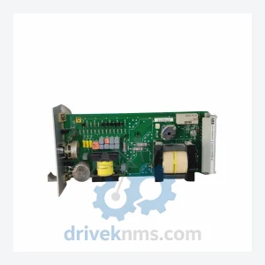
ABB P3LB HENF209568R0001 is listed for Monitoring Systems RFQ review. Confirm quantity, condition and destination before quotation.
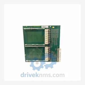
ABB PM154-3BSE003645R1 is listed for Monitoring Systems RFQ review. Confirm quantity, condition and destination before quotation.