
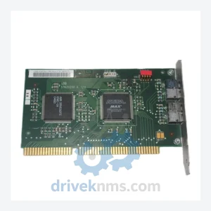
ABB NISA-03 DDCS/ISA Adaptor Module Kit – Obsolete DriveIT Spare Part
ABB NISA-03 is listed for DCS Cards RFQ review. Confirm quantity, condition and destination before quotation.
RFQ-ready industrial model
Model: SDCS-COM-81 3ADT314900R1002
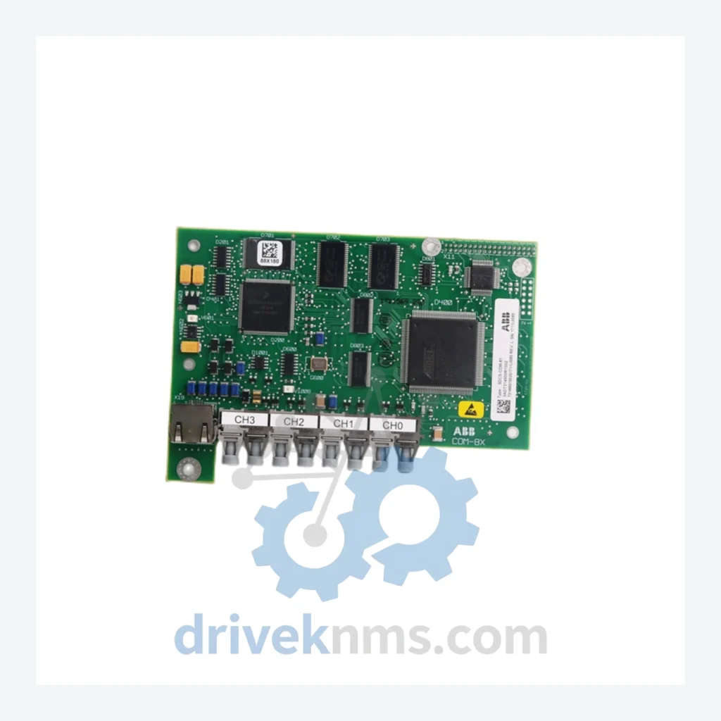
Product Overview
Commercial availability is handled through direct RFQ, model verification and export-oriented follow-up rather than public cart checkout.
Datasheet Preview
Use attached product manuals when available. If the manual is not public yet, request the full file directly through RFQ.
Commercial Path
Product pages on DRIVEKNMS are designed to verify model, brand and series first, then move the buyer into one clean quotation path.
Technical Dossier
The SDCS platform was introduced alongside the DCS 400/500 drive families in the mid-1990s as ABB's response to the need for a modular, field-serviceable DC drive control layer. Early SDCS hardware (Revision A/B boards) used parallel backplane communication with proprietary ABB bus protocols. By the early 2000s, Revision C and D boards introduced improved EMC shielding, extended temperature tolerance, and compatibility with DDCS (Distributed Drive Control System) fiber-optic communication, enabling integration into ABB's broader AC800M and Advant OCS automation architectures.
The SDCS-COM series (communication adapters) evolved to support PROFIBUS-DP, DeviceNet, Modbus RTU, and CANopen fieldbus standards, reflecting the industry's shift toward open-protocol plant networks. The SDCS-CON (control) boards underwent successive revisions to increase closed-loop bandwidth and add adaptive flux control for demanding winding and unwinding applications. As of 2020, ABB has formally classified the DCS 400/500/600 platform as mature/end-of-active-development, with spare parts support continuing through authorized service channels. This lifecycle status makes reliable spare parts sourcing the primary operational concern for maintenance engineers managing installed fleets.
The following SKUs represent the core SDCS module range across control, I/O, communication, and power categories. Each entry reflects a discrete field-replaceable unit within the DCS 400/500/600 drive architecture.
Control Boards (CON)
Communication Adapters (COM)
I/O Boards (IOB)
Power Supply Boards (POW)
Pulse Encoder Interface (PIN)
SDCS modules present specific test challenges due to their integrated backplane bus communication and mixed analog/digital signal paths. DriveKNMS applies the following QC protocol to all SDCS boards prior to dispatch:
Continue The Model Path
Move from this exact model into the matching system hub, brand archive, model-family archive or lifecycle sourcing route before sending a final RFQ list.
Related Paths
ABB NISA-03 is listed for DCS Cards RFQ review. Confirm quantity, condition and destination before quotation.
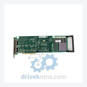
ABB PU514 is listed for DCS Cards RFQ review. Confirm quantity, condition and destination before quotation.
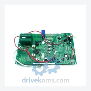
ABB SC300E PAC 031-1053-04 is listed for DCS Cards RFQ review. Confirm quantity, condition and destination before quotation.