
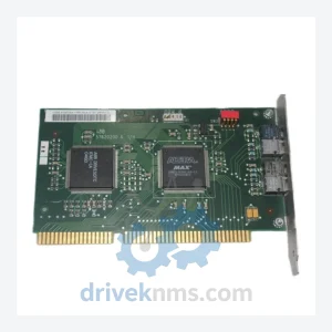
ABB NISA-03 DDCS/ISA Adaptor Module Kit – Obsolete DriveIT Spare Part
ABB NISA-03 is listed for DCS Cards RFQ review. Confirm quantity, condition and destination before quotation.
RFQ-ready industrial model
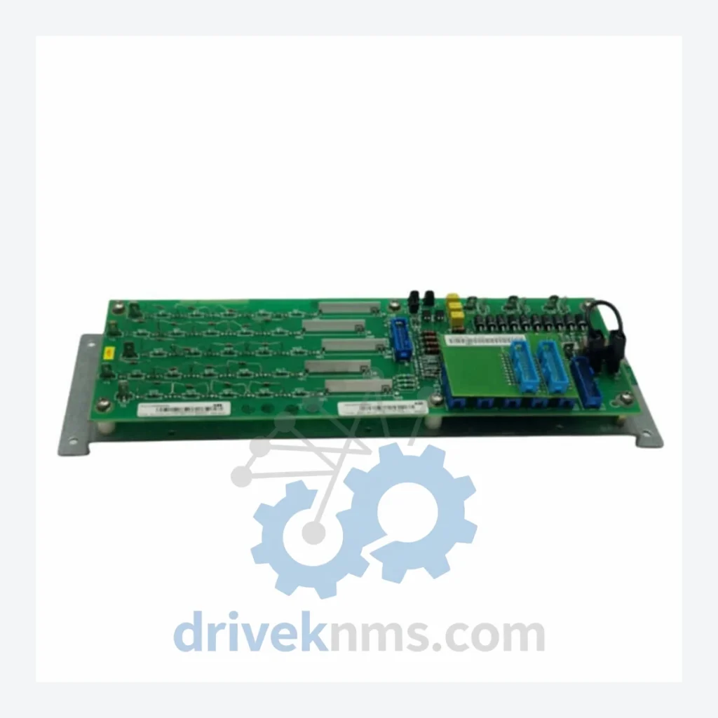
Model: SDCS-PIN-51-COAT
Product Overview
Commercial availability is handled through direct RFQ, model verification and export-oriented follow-up rather than public cart checkout.
Datasheet Preview
Use attached product manuals when available. If the manual is not public yet, request the full file directly through RFQ.
Commercial Path
Product pages on DRIVEKNMS are designed to verify model, brand and series first, then move the buyer into one clean quotation path.
Technical Dossier
The SDCS platform was introduced alongside the DCS500 series in the early 1990s as ABB's standardized control electronics for industrial DC drives. The first-generation SDCS-CON-1 and SDCS-CON-2 boards established the core architecture: a dedicated microprocessor for closed-loop speed and current regulation, with separate I/O expansion via SDCS-IOB plug-in boards. The DCS600 MultiDrive generation (mid-1990s onward) introduced the SDCS-CON-3 and SDCS-CON-4 controllers, which added enhanced fieldbus support (PROFIBUS, DeviceNet, Modbus) via the SDCS-COM adapter slot and expanded analog I/O capacity through the SDCS-IOB-3 and SDCS-IOB-39 boards.
The SDCS-PIN series (Power Interface and Measurement) represents the signal conditioning layer between the drive's power bridge and the control board. The SDCS-PIN-51-COAT is a conformal-coated variant of the SDCS-PIN-51, designed for environments with elevated humidity, condensation risk, or airborne contaminants — common in coastal industrial facilities and chemical processing environments. Conformal coating (IEC 60721-3-3 Class 3C2/3C3 compliance) is applied to the PCB surface to prevent corrosion-induced failure of surface-mount components.
The following SKUs represent the verified SDCS series module range. Each entry reflects a distinct hardware function within the DCS400/DCS600 drive architecture.
Controllers (CON)
Power Interface & Measurement (PIN)
I/O Expansion Boards (IOB)
Communication Adapters (COM)
Power Supply Boards (PSB)
SDCS modules present specific test challenges due to their integration of analog signal conditioning, high-frequency gate pulse circuits, and digital communication buses on a single PCB. DriveKNMS applies the following test protocol to all SDCS units prior to dispatch:
Continue The Model Path
Move from this exact model into the matching system hub, brand archive, model-family archive or lifecycle sourcing route before sending a final RFQ list.
Related Paths
ABB NISA-03 is listed for DCS Cards RFQ review. Confirm quantity, condition and destination before quotation.
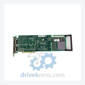
ABB PU514 is listed for DCS Cards RFQ review. Confirm quantity, condition and destination before quotation.
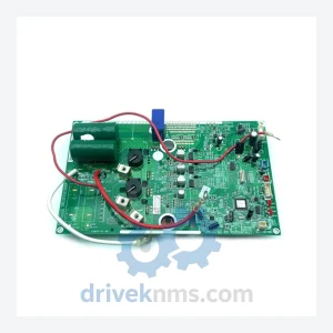
ABB SC300E PAC 031-1053-04 is listed for DCS Cards RFQ review. Confirm quantity, condition and destination before quotation.