
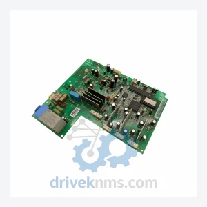
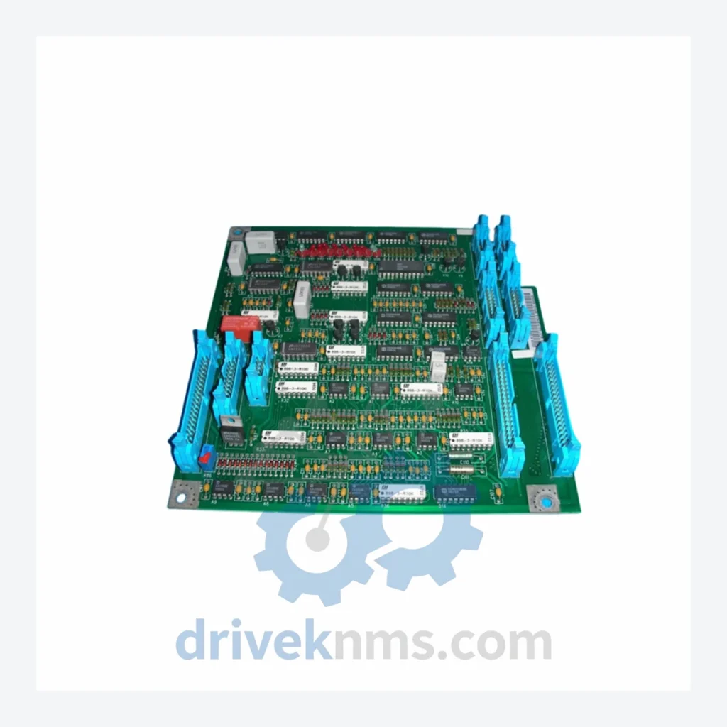
ABB SNAT-7120 Circuit Board – SNAZ7120J Series
ABB SNAT-7120 SNAZ 7120 J SNAZ7120J is listed for SNAZ7120J Series RFQ review. Confirm quantity, condition and destination before quotation.
RFQ-ready industrial model
Model: SNAT620PCB/61033513
Product Overview
Commercial availability is handled through direct RFQ, model verification and export-oriented follow-up rather than public cart checkout.
Datasheet Preview
Use attached product manuals when available. If the manual is not public yet, request the full file directly through RFQ.
Commercial Path
Product pages on DRIVEKNMS are designed to verify model, brand and series first, then move the buyer into one clean quotation path.
Technical Dossier
The SNAT board family was introduced alongside the ACS600 drive platform in the mid-1990s as ABB transitioned from analog-dominant drive control to fully digital ASIC-based architectures. First-generation SNAT boards used parallel backplane communication with proprietary DDCS (Distributed Drive Control System) fiber-optic links for master-follower and fieldbus integration. The ACS800 generation (introduced circa 2000) retained SNAT board form factors and connector pinouts in many positions, enabling partial cross-compatibility — a deliberate design decision that extended the serviceable life of the SNAT ecosystem well into the 2010s.
The following SKUs represent verified, commonly sourced SNAT series modules. Each entry reflects the module's primary functional role within the ACS600/ACS800 drive system.
SNAT620PCB/61033513: ACS600 main control board; handles speed reference processing, I/O interfacing, and DDCS communication backbone.
SNAT601PCB: ACS600 pulse encoder interface board; provides HTL/TTL encoder feedback input for closed-loop vector control.
SNAT602PCB: ACS600 analog I/O expansion board; adds 4 analog inputs and 2 analog outputs for process variable integration.
SNAT603PCB: ACS600 digital I/O expansion board; 8 DI / 6 DO for external interlock and relay logic.
SNAT604PCB: ACS600 DDCS fiber-optic communication board; master link for multi-drive configurations.
SNAT605PCB: ACS600 fieldbus adapter interface board; supports PROFIBUS-DP and Modbus RTU protocol bridging.
SNAT610PCB: ACS600 gate driver interface board; transmits PWM signals to IGBT power module gate units.
SNAT615PCB: ACS600 measurement board; DC bus voltage and phase current sensing for protection logic.
SNAT621PCB: ACS800 main control board (RMIO equivalent predecessor); core processing for scalar and DTC control modes.
SNAT625PCB: ACS800 I/O extension board; expands standard terminal block capacity for complex automation wiring.
SNAT630PCB: ACS800 brake chopper control board; manages dynamic braking resistor switching logic.
SNAT635PCB: ACS800 power supply board; generates internal 24 VDC and ±15 VDC rails for control electronics.
SNAT640PCB: ACS800 SafeStop interface board; implements STO (Safe Torque Off) per IEC 61508 SIL 2.
SNAT645PCB: ACS800 synchronization board; used in multi-drive common DC bus configurations for phase alignment.
SNAT650PCB: ACS800 panel interface board; connects CDP312R and ACS-CP-C control panels to drive control logic.
SNAT660PCB: ACS800 DDCS master board; manages fiber ring topology for up to 12 follower drives.
SNAT series boards present specific test challenges due to their multi-layer PCB construction, ASIC-based logic that cannot be re-flashed in the field, and sensitivity to backplane connector wear. DriveKNMS applies the following test protocol to all SNAT boards prior to dispatch:
Visual inspection: 10x magnification examination of all solder joints, capacitor bodies, and connector pins. Boards with evidence of thermal stress, electrolytic capacitor bulge, or corrosion on DDCS fiber ports are rejected at intake.
Powered bench test: Each board is installed in a matched ACS600 or ACS800 test chassis and powered through a full initialization sequence. Fault memory is read and cleared; all I/O channels are exercised against known reference signals.
DDCS communication verification: Fiber-optic transmit/receive power levels are measured with an optical power meter. Boards with degraded DDCS link performance (<-20 dBm receive sensitivity) are flagged for fiber transceiver replacement.
Firmware version logging: Software version is recorded from the drive parameter set (parameter 33.01 or equivalent) and documented on the board's test certificate to ensure compatibility with the customer's drive revision.
ESD packaging: All boards are shipped in anti-static bags with desiccant, inside rigid foam-lined cartons rated for international air freight.
Continue The Model Path
Move from this exact model into the matching system hub, brand archive, model-family archive or lifecycle sourcing route before sending a final RFQ list.
Related Paths
ABB SNAT-7120 SNAZ 7120 J SNAZ7120J is listed for SNAZ7120J Series RFQ review. Confirm quantity, condition and destination before quotation.
ABB PM564-TP-ETH 1SAP121100R0071 is listed for Servo Drives RFQ review. Confirm quantity, condition and destination before quotation.
ABB SCDCS-CON-4 is listed for CON-4 Control Board RFQ review. Confirm quantity, condition and destination before quotation.