
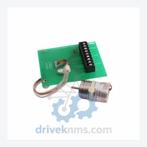
Amci R11X-J10/7
Amci R11X-J10/7 is listed for Servo Drives RFQ review. Confirm quantity, condition and destination before quotation.
RFQ-ready industrial model
Model: R11X-J10/7G
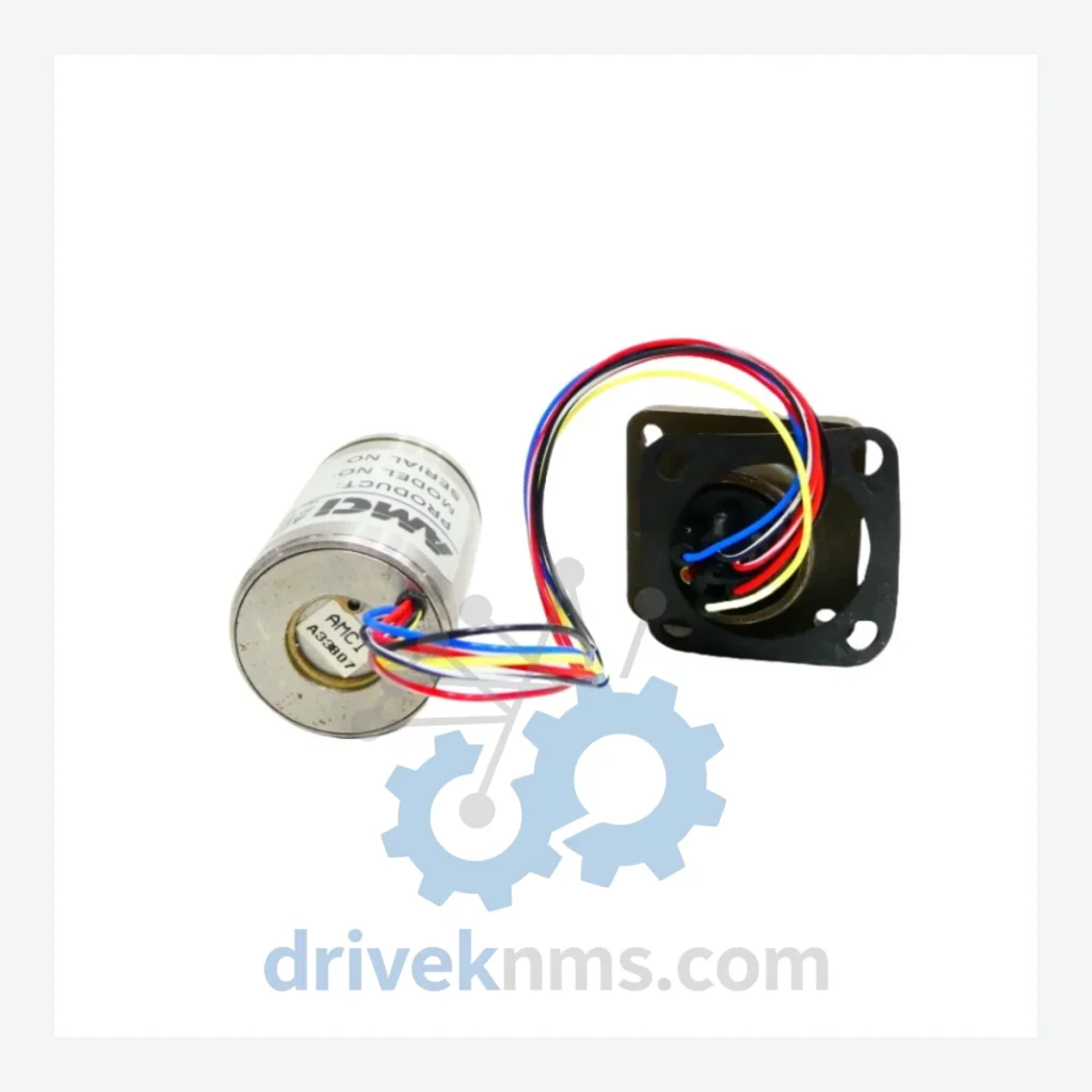
Product Overview
Commercial availability is handled through direct RFQ, model verification and export-oriented follow-up rather than public cart checkout.
Datasheet Preview
Use attached product manuals when available. If the manual is not public yet, request the full file directly through RFQ.
Commercial Path
Product pages on DRIVEKNMS are designed to verify model, brand and series first, then move the buyer into one clean quotation path.
Technical Dossier
DriveKNMS reviews sourcing options for this model during RFQ handling before quotation.
RFQ support for obsolete parts: Send the model number, required quantity and destination so DriveKNMS can confirm sourcing options before quotation.
| Manufacturer | Advanced Micro Controls Inc. (AMCI) |
| Part Number | R11X-J10/7G |
| Series | R11X |
| Function | Resolver-to-Digital Converter (RDC) / Motion Control Interface Module |
| Form Factor | Rack-mount module; compatible with AMCI backplane systems |
| Resolver Input | Single-speed resolver input |
| Output Interface | Parallel digital position output; compatible with host PLC/controller backplane |
| Country of Origin | United States |
| OEM Status | Discontinued – no longer in active production |
| Typical Host Systems | Allen-Bradley PLC-5, SLC 500, early ControlLogix platforms; legacy AMCI motion control racks |
Note: Electrical parameters not independently verified by DriveKNMS are intentionally omitted. Specifications above are based on documented product family data. Buyers requiring full datasheet confirmation should contact us prior to purchase.
The AMCI R11X series was designed for an era when resolver-based feedback was the standard for precision rotary positioning in industrial automation. These modules provided the critical interface layer between mechanical resolvers mounted on servo motors or rotary tables and the digital control logic of the host PLC or motion controller. In systems where this architecture is still operational — and there are thousands of such installations across automotive stamping, packaging machinery, printing presses, and material handling — the R11X-J10/7G is not interchangeable with modern SSI or EnDat encoder interfaces without significant hardware and software rework.
The R11X-J10/7G is particularly prevalent in installations paired with Allen-Bradley PLC-5 and SLC 500 controllers, where the AMCI rack module communicated position data directly over the backplane. Migrating away from this architecture requires not only new hardware but re-validation of all position-dependent control logic — a process that cannot be compressed without risk.
Sourcing a verified R11X-J10/7G spare from DriveKNMS provides a direct path to restoring production without triggering a capital project. For facilities with multiple axes using this module, establishing a minimum two-unit on-site buffer is the standard recommendation for lifecycle risk management.
Discontinued modules sourced from the secondary market carry inherent risks: electrolytic capacitor degradation, firmware version mismatches, connector pin corrosion, and undisclosed prior damage. DriveKNMS applies a structured 5-step QA process to every R11X-J10/7G unit before it leaves our facility.
Continue The Model Path
Move from this exact model into the matching system hub, brand archive, model-family archive or lifecycle sourcing route before sending a final RFQ list.
Related Paths
Amci R11X-J10/7 is listed for Servo Drives RFQ review. Confirm quantity, condition and destination before quotation.
Amci SD3520 is listed for Servo Drives RFQ review. Confirm quantity, condition and destination before quotation.
Amci 8213 is listed for 8200 Series RFQ review. Confirm quantity, condition and destination before quotation.