
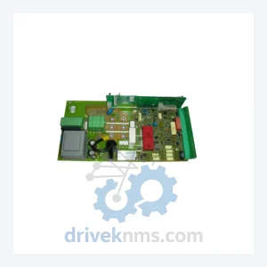
ANSALDO ELC260491 ELC260590 PLC Module – Automation Control
Ansaldo ELC260491 ELC260590 is listed for PLC Modules RFQ review. Confirm quantity, condition and destination before quotation.
RFQ-ready industrial model
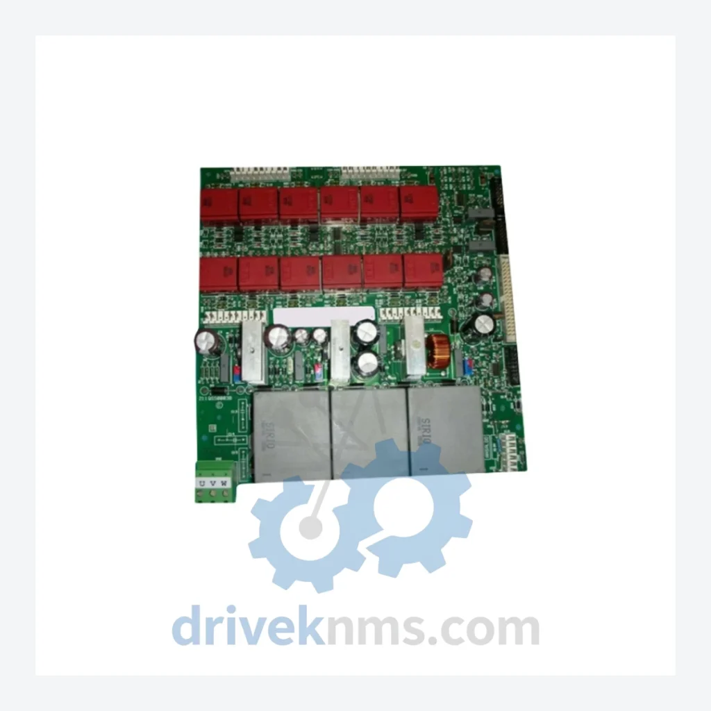
Model: 211QS50003B
Product Overview
Commercial availability is handled through direct RFQ, model verification and export-oriented follow-up rather than public cart checkout.
Datasheet Preview
Use attached product manuals when available. If the manual is not public yet, request the full file directly through RFQ.
Commercial Path
Product pages on DRIVEKNMS are designed to verify model, brand and series first, then move the buyer into one clean quotation path.
Technical Dossier
The ANSALDO 211QS series represents a core hardware platform deployed across heavy industrial installations worldwide, including petrochemical refineries, nuclear power stations, steel mills, and offshore processing facilities. Manufactured by Ansaldo Sistemi Industriali (ASI) — a division with deep roots in Italian industrial automation — the 211QS platform was engineered to serve as the backbone of distributed control and drive systems in environments where continuous uptime is non-negotiable. Its modular backplane architecture allows individual boards to be replaced without full system shutdown, a critical design requirement for facilities operating 24/7 with zero-tolerance for unplanned outages. The series has been installed in legacy DCS and thyristor drive control cabinets across Europe, Asia, and the Middle East, and remains in active service at sites where full system replacement is economically or operationally impractical.
The 211QS series emerged from ANSALDO's drive control engineering lineage in the 1980s and 1990s, designed to interface with thyristor-based DC drive systems and early DCS platforms. Early revisions of the 211QS boards used through-hole component technology with discrete analog signal conditioning circuits. Mid-generation revisions introduced surface-mount components, improved EMI shielding, and enhanced optocoupler isolation for gate trigger circuits — directly relevant to the 211QS50003B Power Trigger Board, which handles firing pulse generation for thyristor bridges.
The following SKUs represent verified models within the ANSALDO 211QS series, classified by functional category. Each model is a discrete board-level replacement unit.
Power & Trigger Boards
Analog I/O & Signal Conditioning
Digital I/O Modules
Communication & CPU Boards
Power Supply Boards
The 211QS series presents specific quality control challenges due to its mixed analog/digital architecture and the age profile of available inventory. DriveKNMS applies a structured test protocol to all 211QS boards prior to dispatch:
Continue The Model Path
Move from this exact model into the matching system hub, brand archive, model-family archive or lifecycle sourcing route before sending a final RFQ list.
Related Paths
Ansaldo ELC260491 ELC260590 is listed for PLC Modules RFQ review. Confirm quantity, condition and destination before quotation.
Ansaldo ELC260491 + ELC260590 is listed for ELC Series RFQ review. Confirm quantity, condition and destination before quotation.
Alstom MVAJ105RA0802A is listed for MiCOM Series RFQ review. Confirm quantity, condition and destination before quotation.