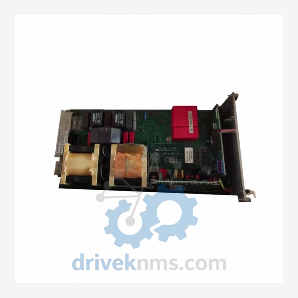
ATOTECH MG330 Modules MG330TD40-B

Model: MG330TD40-B

Brand Atotech
Series MG330
Model MG330TD40-B
RFQ-ready model route Obsolete and surplus sourcing Export follow-up by model list

Product Overview

Commercial availability is handled through direct RFQ, model verification and export-oriented follow-up rather than public cart checkout.

Datasheet Preview

Datasheet Preview

Use attached product manuals when available. If the manual is not public yet, request the full file directly through RFQ.

Request Full Manual

Commercial Path

Use This Page To Confirm The Model, Then Move To RFQ

Product pages on DRIVEKNMS are designed to verify model, brand and series first, then move the buyer into one clean quotation path.

Technical Dossier

Product Details And Specifications

ATOTECH MG330 Series Technical Notes

The Evolution of MG330 Architecture

The MG330 platform was introduced as a successor to earlier ATOTECH relay-logic and discrete control panels, transitioning the product line into programmable, rack-mounted modular control. Early revisions of the MG330 family used parallel backplane communication with fixed-address I/O mapping, which imposed slot-position dependencies during system configuration. Subsequent hardware revisions introduced serial backplane variants with auto-addressing capability, reducing commissioning time and enabling hot-swap replacement of select module types without full system shutdown.

MG330 Full Catalog & Functionalities (SKU List)

The following SKUs represent verified models within the ATOTECH MG330 control platform, classified by functional category:

Digital Output Modules (Transistor)

  • MG330TD40-B: 40-channel transistor digital output control card, 24 VDC, DIN-rail compatible backplane mount.
  • MG330TD32-A: 32-channel transistor digital output module, standard rack format, 24 VDC sourcing.
  • MG330TD16-C: 16-channel transistor output card, compact form factor, short-circuit protection per channel.
  • MG330TD08-B: 8-channel transistor output module, high-current variant, 0.5 A per channel rating.

Digital Input Modules

  • MG330DI40-A: 40-channel digital input module, 24 VDC sink/source configurable, optical isolation.
  • MG330DI32-B: 32-channel digital input card, high-speed capture mode, 1 ms filter selectable.
  • MG330DI16-A: 16-channel digital input module, standard backplane interface, LED status per channel.
  • MG330DI08-C: 8-channel digital input card, extended temperature range variant (-20 °C to +60 °C).

Analog I/O Modules

  • MG330AI08-B: 8-channel analog input module, 4–20 mA / 0–10 V selectable, 12-bit resolution.
  • MG330AI04-A: 4-channel analog input card, differential input configuration, 14-bit resolution.
  • MG330AO08-A: 8-channel analog output module, 4–20 mA current loop, 12-bit DAC.
  • MG330AO04-B: 4-channel analog output card, voltage/current dual-mode output, isolated per channel.

CPU / Controller Modules

  • MG330CPU-01: Main CPU module, ladder logic execution, 256 KB program memory, RS-232/RS-485 ports.
  • MG330CPU-02: Enhanced CPU module, extended memory (512 KB), Ethernet option slot, real-time clock.

Communication & Power Modules

  • MG330COM-RS: RS-485 multi-drop communication adapter, Modbus RTU master/slave, 32-node support.
  • MG330PSU-24: 24 VDC rack power supply module, 5 A output, over-voltage and short-circuit protection.
  • MG330PSU-48: 48 VDC power supply variant for high-drive output configurations.

Quality Control for the MG330 Range

MG330 modules present specific test challenges due to their backplane-dependent communication architecture and mixed-signal I/O designs. DriveKNMS applies a structured verification protocol to all MG330 units prior to dispatch:

  • Backplane Interface Test: Each module is seated in a reference MG330 rack and subjected to full backplane communication cycling to verify address recognition and data integrity.
  • Channel-Level Functional Test: All I/O channels are individually exercised. Digital output modules (including MG330TD40-B) are tested under resistive load at rated current. Analog modules are verified against calibrated reference signals at 0%, 50%, and 100% of input/output range.
  • Isolation Resistance Check: Optical isolation barriers on digital input modules are tested at 500 VDC to confirm dielectric integrity.
  • Thermal Burn-In: Select modules undergo 48-hour powered burn-in at 40 °C ambient to screen early-life failures common in aged electrolytic capacitors.
  • Visual and Component Inspection: PCB surfaces are inspected under magnification for corrosion, cold solder joints, and capacitor bulge — failure modes prevalent in modules recovered from humid industrial environments.

All test results are documented and supplied with each unit shipment on request.

Continue The Model Path

Use system, brand and series routes to compare related published models.

Move from this exact model into the matching system hub, brand archive, model-family archive or lifecycle sourcing route before sending a final RFQ list.

WhatsApp Prefilled Inquiry Email sale@driveknms.com Phone +86 18359293191 Top Back To Top