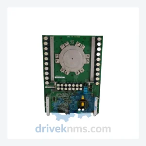
Basler Electric 81001-451-62-R Current Transformer Set – Obsolete 1500A SGCT Spare Part
Basler Electric 81001-451-62-R Current Transformer Set – Obsolete 1500A SGCT Spare Part When a generator protection relay system loses its…
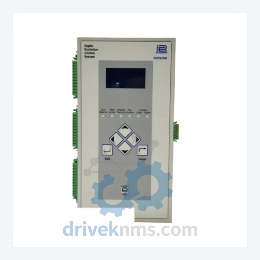
Model: DECS-250-LN1SN1N
Product Overview
Commercial availability is handled through direct RFQ, model verification and export-oriented follow-up rather than public cart checkout.
Datasheet Preview
Use attached product manuals when available. If the manual is not public yet, request the full file directly through RFQ.
Commercial Path
Product pages on DRIVEKNMS are designed to verify model, brand and series first, then move the buyer into one clean quotation path.
Technical Dossier
The Basler Electric DECS-250 is a microprocessor-based Digital Excitation Control System (DECS) designed for synchronous generators operating in power generation facilities, including fossil fuel power plants, hydroelectric stations, nuclear auxiliary systems, and petrochemical co-generation units. The DECS-250 platform holds a significant installed base across North American and Southeast Asian heavy industrial sites, where it replaced legacy analog voltage regulators (AVRs) from the 1980s and 1990s. Its modular architecture supports both brushless and static excitation systems, making it a cross-platform solution for OEM turbine-generator packages from GE, Siemens, and Mitsubishi.
Basler Electric introduced the DECS-200 platform in the mid-1990s as a successor to the analog SSB and SCP series regulators. The DECS-250 represents the second-generation digital architecture, incorporating a 32-bit DSP core, expanded I/O capacity, and IEEE 421.5-compliant PID excitation control loops. Key architectural milestones include:
Compatibility note: DECS-250 firmware versions prior to 1.06.xx are not compatible with BESTCOMS Plus software. Sites running legacy firmware must use BESTCOMS for Windows v4.x or earlier.
The following SKUs represent the verified active and legacy catalog for the DECS-250 platform, classified by functional category. All models listed below are genuine Basler Electric part numbers.
Base Control Units
Redundant & Enhanced Configurations
Communication & Accessory Modules
Several DECS-250 communication modules and early base unit variants (pre-2008 manufacture dates) have been discontinued by Basler Electric. DriveKNMS maintains a dedicated inventory of tested surplus and refurbished DECS-250 units to support lifecycle extension for sites that cannot migrate to the DECS-400 platform due to control room integration constraints or capital expenditure limitations.
DriveKNMS sourcing capabilities for the DECS-250 range include:
The DECS-250 platform uses a proprietary backplane bus for inter-module communication. Standard bench testing procedures are insufficient to validate backplane integrity and DSP firmware state. DriveKNMS applies the following test protocol to all DECS-250 units prior to dispatch:
© 2026 DriveKNMS. All trademarks belong to their respective owners. Specifications are for reference only and subject to change without notice. Verify all parameters against official documentation before installation.
Related Paths
Basler Electric 81001-451-62-R Current Transformer Set – Obsolete 1500A SGCT Spare Part When a generator protection relay system loses its…
Basler DECS-250-LN2SN1N Digital Excitation Control System – DECS-250 Series In power generation facilities — whether gas turbines, steam turbines, or…
ALSTOM MVAJ105RA0802A Protection Relay: Supply Continuity Strategy for a Discontinued Critical Component The ALSTOM MVAJ105RA0802A is a numerical protection relay…