Technical Dossier
Product Details And Specifications
Bosch Rexroth DKC02.3 Series Technical Notes
The Evolution of DKC02.3 Architecture
The DKC02.3 is the second-generation compact drive within Rexroth's ECODRIVE Cs lineage, succeeding the DKC01.1 and DKC02.1 platforms introduced in the mid-1990s. The .3 revision introduced a unified firmware architecture (FW) that consolidated motion task management, parameter handling, and fieldbus communication into a single embedded controller, eliminating the need for separate motion control cards used in earlier generations.
Key architectural milestones: the original DKC01.1 relied on external motion controllers and offered limited onboard diagnostics. The DKC02.1 introduced onboard parameter memory and basic PROFIBUS support. The DKC02.3 added SERCOS II compatibility, expanded I/O mapping, and the /S10 safety option — a hardware-level Safe Torque Off (STO) circuit compliant with EN 954-1 Category 3. The /S10 suffix denotes drives equipped with this integrated safety relay module, which became mandatory in many EU machinery directive applications post-2006.
The DKC02.3 series entered its end-of-production phase circa 2012–2015, with Bosch Rexroth transitioning customers toward the IndraDrive Cs (HCS01) and IndraDrive C (HCS02/HCS03) platforms. However, due to the extensive installed base in legacy machinery, demand for DKC02.3 spare units and tested replacements remains active through specialist distributors.
DKC02.3 Full Catalog & Functionalities (SKU List)
The following SKUs represent verified models within the Bosch Rexroth DKC02.3 ECODRIVE Cs series. Units are classified by current rating, firmware variant, and safety option:
DKC02.3-040-7-FW: 40A continuous output, standard firmware, SERCOS/analog interface, no safety option.
DKC02.3-040-7-FW/S10: 40A output with integrated STO (Safe Torque Off) safety relay module.
DKC02.3-100-7-FW: 100A continuous output, standard firmware, suitable for mid-range servo motors up to 7.5 kW.
DKC02.3-100-7-FW/S10: 100A output with EN 954-1 Cat.3 STO safety circuit integrated.
DKC02.3-200-7-FW: 200A peak output, standard firmware, high-torque axis control for heavy-duty servo applications.
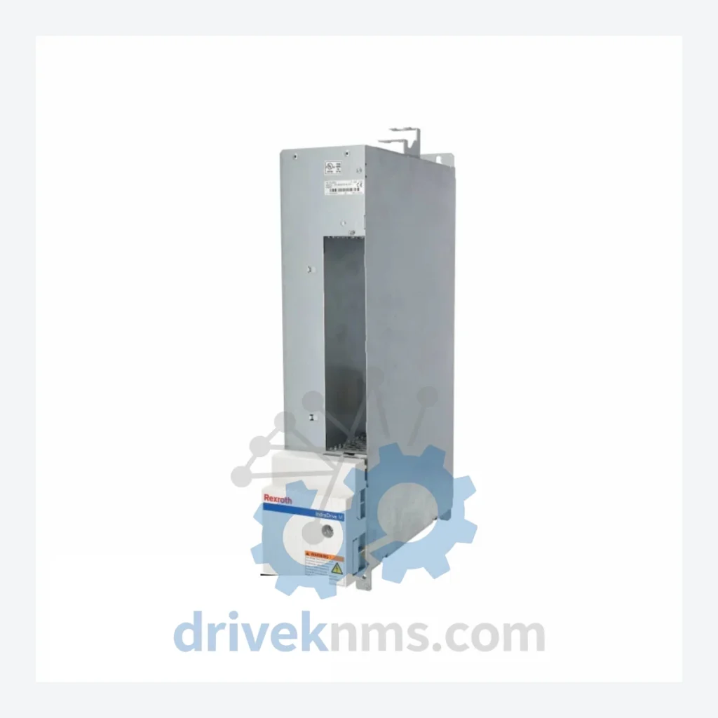
DKC02.3-200-7-FW/S10: 200A output with /S10 safety module — the specific unit covered by this listing.
DKC02.3-040-7-FW/S10-00: 40A, safety option, variant with extended parameter set for multi-axis synchronization.
DKC02.3-100-7-FW/S10-00: 100A, safety option, extended parameter variant.
DKC02.3-200-7-FW/S10-00: 200A, safety option, extended parameter variant with additional I/O mapping.
DKC02.3-040-7-FW-B: 40A, firmware variant B, PROFIBUS-DP primary fieldbus configuration.
DKC02.3-100-7-FW-B: 100A, firmware variant B, PROFIBUS-DP primary fieldbus configuration.
DKC02.3-200-7-FW-B: 200A, firmware variant B, PROFIBUS-DP primary fieldbus configuration.
DKC02.3-040-7-FW/S10-B: 40A, PROFIBUS-DP, with STO safety relay module.
DKC02.3-100-7-FW/S10-B: 100A, PROFIBUS-DP, with STO safety relay module.
DKC02.3-200-7-FW/S10-B: 200A, PROFIBUS-DP, with STO safety relay module — high-current PROFIBUS safety variant.
DKC02.3-040-7-FW/S10-C: 40A, SERCOS II interface, safety option, compact panel-mount configuration.
DKC02.3-100-7-FW/S10-C: 100A, SERCOS II interface, safety option, for synchronized multi-axis SERCOS rings.
Sourcing Hard-to-Find & Obsolete DKC02.3 Parts
For operators running DKC02.3-based machinery beyond the OEM support window, DriveKNMS provides: direct unit replacement with tested equivalents, cross-reference matching for /S10 safety variants, firmware version verification prior to dispatch, and documentation support for CE re-certification where required. All units are catalogued by current rating, firmware revision, and safety option to ensure exact-match replacement without machine reconfiguration.
Quality Control for the DKC02.3 Range
Each DKC02.3 unit processed by DriveKNMS undergoes a structured test protocol designed around the specific electrical and communication architecture of the ECODRIVE Cs platform. Testing procedures include: DC bus capacitor ESR measurement and reformation where applicable; IGBT gate driver integrity check under load simulation; SERCOS and PROFIBUS-DP communication handshake verification using Rexroth IndraWorks diagnostic software; STO circuit continuity and response-time validation for /S10 variants (measured against EN 954-1 Category 3 timing thresholds); parameter memory read/write cycle test; and thermal imaging under 30-minute operational load to identify latent component degradation. Units that do not pass all stages are quarantined and not offered for sale.