BENDER VMD420-D-2 Voltage Relay – Symmetrical Component Relay
BENDER VMD420-D-2 Voltage Relay: Global Sourcing Strategy & Asset Return Value The BENDER VMD420-D-2 is a symmetrical component relay engineered…
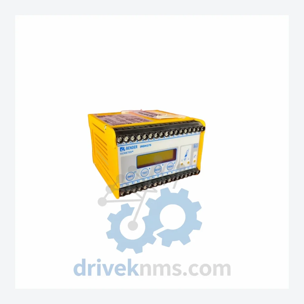
Model: IRDH275B-425
Product Overview
Commercial availability is handled through direct RFQ, model verification and export-oriented follow-up rather than public cart checkout.
Datasheet Preview
Use attached product manuals when available. If the manual is not public yet, request the full file directly through RFQ.
Commercial Path
Product pages on DRIVEKNMS are designed to verify model, brand and series first, then move the buyer into one clean quotation path.
Technical Dossier
The BENDER IRDH275B series represents one of the most widely deployed insulation monitoring device (IMD) families in global heavy industry. Installed across chemical processing plants, nuclear power stations, oil refineries, offshore platforms, and large-scale manufacturing facilities, the IRDH275B line operates on the principle of continuous insulation resistance monitoring in unearthed (IT) power systems — a mandatory safety requirement in IEC 61557-8 compliant installations. Its adoption in critical infrastructure is driven by its ability to detect insulation faults before a second fault can cause a dangerous touch voltage or system shutdown. The series covers AC, DC, and AC/DC system variants, with rated system voltages spanning from 24 V to 690 V AC and up to 1000 V DC, making it applicable across low-voltage switchgear, drive systems, and medical-grade power distribution.
BENDER's insulation monitoring product line traces its origins to the IRDH265 and IRDH275 platforms, which established the core AMP (Adaptive Measuring Principle) technology used to suppress interference from system capacitances — a persistent challenge in large IT networks with high leakage capacitance. The IRDH275B generation introduced a fully digital measurement engine, replacing the earlier analog threshold circuits with a microcontroller-based evaluation unit. This transition enabled configurable response values (1 kΩ to 10 MΩ), dual-channel alarm relay outputs, and RS-485 / Modbus RTU communication as standard features rather than optional add-ons.
The "B" suffix in IRDH275B denotes the second-generation platform with enhanced EMC immunity (EN 61326-1), wider operating temperature range (−25 °C to +70 °C), and compatibility with BENDER's BMS (BENDER Measuring System) bus for integration into the COM465 and CP700 communication modules. Compared to the predecessor IRDH275, the IRDH275B added a test function per IEC 61557-8, self-monitoring diagnostics, and a standardized DIN rail or panel-mount form factor. The series is now in a mature/end-of-active-development phase; BENDER's current active platform is the IRDH575 and ISOMETER® iso685 family. However, the IRDH275B remains in active spare parts supply due to the long operational life of the IT systems it monitors — many installations have 20–30 year design lives.
The following SKUs represent the verified IRDH275B product range. Each unit is an insulation monitoring device; variant suffixes define the rated system voltage and coupling network configuration:
IRDH275B-425: IMD for AC/DC IT systems, Un = 42.5–460 V AC / 42.5–600 V DC, AMP technology, dual alarm relay, RS-485
IRDH275B-427: IMD for AC IT systems, Un = 42.5–460 V AC, optimized for high-capacitance networks, Modbus RTU
IRDH275B-435: IMD for DC IT systems, Un = 42.5–600 V DC, suitable for battery and drive DC buses
IRDH275B-437: IMD for AC/DC IT systems, Un = 42.5–460 V AC / 42.5–600 V DC, extended temperature variant
IRDH275B-440: IMD for AC IT systems, Un = 100–690 V AC, high-voltage range, dual relay output
IRDH275B-443: IMD for AC/DC IT systems, Un = 100–690 V AC / 100–1000 V DC, high-voltage DC drive applications
IRDH275B-445: IMD for AC IT systems, Un = 100–690 V AC, panel-mount variant with analog output 0–20 mA
IRDH275B-447: IMD for DC IT systems, Un = 100–1000 V DC, photovoltaic and renewable energy DC systems
IRDH275B-450: IMD for AC/DC IT systems, Un = 42.5–460 V AC, with integrated BMS bus interface
IRDH275B-453: IMD for AC IT systems, Un = 42.5–460 V AC, ATEX-compatible coupling for hazardous area installations
IRDH275B-457: IMD for AC/DC IT systems, Un = 42.5–460 V AC / 42.5–600 V DC, with 4–20 mA analog output
IRDH275B-460: IMD for AC IT systems, Un = 100–690 V AC, with RS-485 and BMS bus dual interface
IRDH275B-463: IMD for DC IT systems, Un = 42.5–600 V DC, marine and offshore variant (DNV GL type approval)
IRDH275B-467: IMD for AC/DC IT systems, Un = 100–690 V AC / 100–1000 V DC, high-voltage marine variant
IRDH275B-470: IMD for AC IT systems, Un = 42.5–460 V AC, medical IT system variant per IEC 61557-8 / IEC 60364-7-710
The IRDH275B series has entered the mature phase of its product lifecycle. BENDER has transitioned its active development to the ISOMETER® iso685 and IRDH575 platforms. As a result, certain IRDH275B variants — particularly those with ATEX ratings, marine type approvals, or legacy BMS bus configurations — are no longer available through standard distribution channels and carry extended lead times from the OEM.
Insulation monitoring devices present specific verification challenges that differ from standard relay or I/O module testing. The IRDH275B units processed by DriveKNMS undergo a structured test protocol that addresses the following:
Insulation Resistance Measurement Accuracy: Each unit is connected to a calibrated IT network simulator. Resistance values at 1 kΩ, 10 kΩ, 100 kΩ, and 1 MΩ are injected and the device response value is verified against the factory specification (±15% tolerance per IEC 61557-8).
Alarm Relay Function: Both alarm relays (Alarm 1 and Alarm 2) are cycled through trip and reset sequences at the configured threshold. Contact resistance and switching time are recorded.
AMP Interference Suppression: A capacitive load (simulating a large IT network) is applied to verify that the AMP algorithm correctly compensates for system capacitance and does not generate false alarms.
RS-485 / Modbus RTU Communication: Register map read/write operations are executed using a Modbus master to confirm correct response to standard function codes (FC03, FC06, FC16).
Power Supply Range: Units are tested at the lower and upper limits of the rated auxiliary supply voltage (typically 24 V AC/DC and 240 V AC) to confirm stable operation across the full input range.
Self-Monitoring Diagnostics: The internal self-test function (per IEC 61557-8 Clause 6.5) is triggered and the device response is verified.
© 2026 DriveKNMS. All trademarks belong to their respective owners. Specifications are for reference only and subject to change without notice. Verify all parameters against official documentation before installation.
Related Paths
BENDER VMD420-D-2 Voltage Relay: Global Sourcing Strategy & Asset Return Value The BENDER VMD420-D-2 is a symmetrical component relay engineered…
Bender IRDH275-427 Insulation Monitoring Relay – Obsolete ISOMETER Series Spare Part When the IRDH275-427 fails in an ungrounded (IT) power…
Bender IRDH275B-427 Insulation Monitoring Device – Obsolete IRDH Series Spare Part When the IRDH275B-427 fails in an ungrounded DC or…