
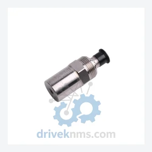
Bently Nevada 190501 Velomitor CT Modules – 190501-04-00-CN
Bently Nevada 190501-04-00-CN is listed for Velomitor CT RFQ review. Confirm quantity, condition and destination before quotation.
RFQ-ready industrial model
Model: 128075-01E
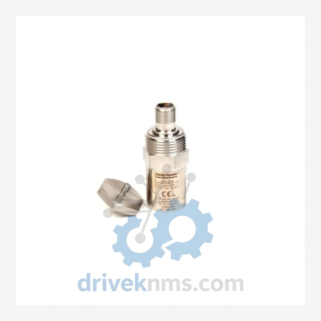
Product Overview
Commercial availability is handled through direct RFQ, model verification and export-oriented follow-up rather than public cart checkout.
Datasheet Preview
Use attached product manuals when available. If the manual is not public yet, request the full file directly through RFQ.
Commercial Path
Product pages on DRIVEKNMS are designed to verify model, brand and series first, then move the buyer into one clean quotation path.
Technical Dossier
The Bently Nevada Velomitor CT series is a family of piezoelectric velocity transducers engineered for continuous vibration monitoring in heavy industrial environments. Deployed across petrochemical refineries, nuclear power stations, offshore platforms, and large-scale rotating machinery installations, the Velomitor CT has established a dominant position as a field-proven velocity sensor compatible with Bently Nevada 3300, 3500, and ADAPT.wind monitoring systems. Its wide operating voltage range (10–24 VDC) and low current draw (5 mA max) make it suitable for both legacy and modern machinery protection architectures. The series is manufactured to API 670 machinery protection standards and is routinely specified in turbine, compressor, pump, and motor monitoring applications where non-contact eddy-current proximity probes are impractical or cost-prohibitive.
The Velomitor CT (Current Transmitter) platform was developed by Bently Nevada as a direct successor to earlier seismic velocity transducer designs that relied on moving-coil electromagnetic principles. The CT designation distinguishes this series from voltage-output Velomitor variants: the CT transmits a 4–20 mA current-loop signal proportional to vibration velocity, enabling long cable runs without signal degradation — a critical requirement in large plant installations where sensor-to-rack distances routinely exceed 300 meters.
Early Velomitor designs (pre-2000) used analog signal conditioning with limited EMI rejection. The CT architecture introduced integrated ASIC-based signal processing, improving frequency response linearity across the 2–1000 Hz measurement band. Subsequent revisions addressed connector standardization (transitioning from MIL-spec to M12 industrial connectors on select variants) and extended the operating temperature range to –50°C / +121°C to accommodate cryogenic and high-temperature process environments.
Compatibility note: Velomitor CT transducers are backward-compatible with Bently Nevada 3300 series monitor inputs configured for 4–20 mA velocity input. Integration with 3500/40M and 3500/42M velocity monitor cards requires verification of input impedance and loop supply voltage. Older 7200 series systems may require signal conditioning adapters.
The following SKUs represent the verified Velomitor CT product range. Each model is classified by mounting configuration, connector type, cable length, and operating specification.
128075-01E: Velomitor CT, 10–24 VDC, 5 mA max, standard industrial housing, side-exit cable, metric thread mount — primary stocking SKU for general rotating machinery applications.
128075-01: Velomitor CT, base configuration without revision suffix, functionally equivalent to -01E; earlier production lot identifier used in pre-2010 procurement documentation.
128075-02: Velomitor CT, extended temperature variant, –50°C to +121°C operating range, suitable for cryogenic compressor and steam turbine bearing housings.
128075-03: Velomitor CT, stainless steel housing, IP68-rated, designed for wash-down and submerged bearing housing environments in pulp, paper, and food processing.
128075-04: Velomitor CT, ATEX/IECEx Zone 1 certified, intrinsically safe barrier required, for use in explosive atmosphere classified areas (gas groups IIA/IIB).
128075-05: Velomitor CT, M12 4-pin connector output (no integral cable), for installations requiring field-replaceable cable assemblies.
128075-06: Velomitor CT, 5-meter integral armored cable, stainless steel braid, for high-vibration mounting locations where cable protection is mandatory.
128075-07: Velomitor CT, 10-meter integral cable variant, used in large turbine pedestals where extended cable routing is required without junction boxes.
128075-08: Velomitor CT, dual-output configuration, simultaneous 4–20 mA and 0–10 V outputs for parallel connection to DCS analog input and local display.
128075-09: Velomitor CT, high-frequency variant, extended bandwidth to 2000 Hz, for gearbox and rolling element bearing applications requiring higher frequency resolution.
128075-10: Velomitor CT, low-profile housing, reduced radial envelope for space-constrained bearing housings on smaller rotating equipment.
128075-11: Velomitor CT, CSA/UL certified variant for North American hazardous location compliance (Class I, Division 2).
128075-12: Velomitor CT, side-entry NPT conduit fitting, for installations requiring rigid conduit connection per NEC standards.
128075-13: Velomitor CT, high-temperature variant rated to +150°C continuous, for steam turbine exhaust-end bearing monitoring.
128075-14: Velomitor CT, seawater-resistant coating, for offshore marine platform applications with salt-spray exposure per IEC 60068-2-52.
128075-15: Velomitor CT, factory-calibrated with NIST-traceable certificate, for applications requiring documented metrology chain (nuclear, aerospace, defense).
Velomitor CT transducers present specific verification challenges due to their integrated current-loop signal conditioning circuitry. Standard passive resistance checks are insufficient to confirm functional integrity. DriveKNMS applies the following test protocol to all Velomitor CT units prior to dispatch:
Loop supply energization at 24 VDC with precision current measurement to verify quiescent current draw within specification (≤5 mA). Vibration stimulus testing using a calibrated shaker table at reference frequencies (10 Hz, 100 Hz, 1000 Hz) to confirm output linearity and sensitivity (typically 100 mV/mm/s or 4–20 mA equivalent). Insulation resistance test between signal conductors and housing ground (≥100 MΩ at 500 VDC). Connector and cable integrity inspection including pull-force test on integral cable terminations. Dimensional verification of mounting thread (M8 or 1/4-28 UNF per variant) to confirm mechanical fit. Each unit is issued a test record traceable to the unit serial number and stored for customer audit access.
Continue The Model Path
Move from this exact model into the matching system hub, brand archive, model-family archive or lifecycle sourcing route before sending a final RFQ list.
Related Paths
Bently Nevada 190501-04-00-CN is listed for Velomitor CT RFQ review. Confirm quantity, condition and destination before quotation.
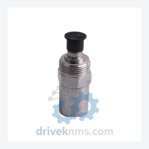
Bently Nevada 190501-04-00-04 is listed for Velomitor CT RFQ review. Confirm quantity, condition and destination before quotation.

Bently Nevada 190501-02-99-00 is listed for Velomitor CT RFQ review. Confirm quantity, condition and destination before quotation.