Bombardier 3EST Series Modules: 3EST000212-0728
Bombardier 3EST Series: Comprehensive Module Range and Technical Overview The Bombardier 3EST series represents a core family of input/output and…
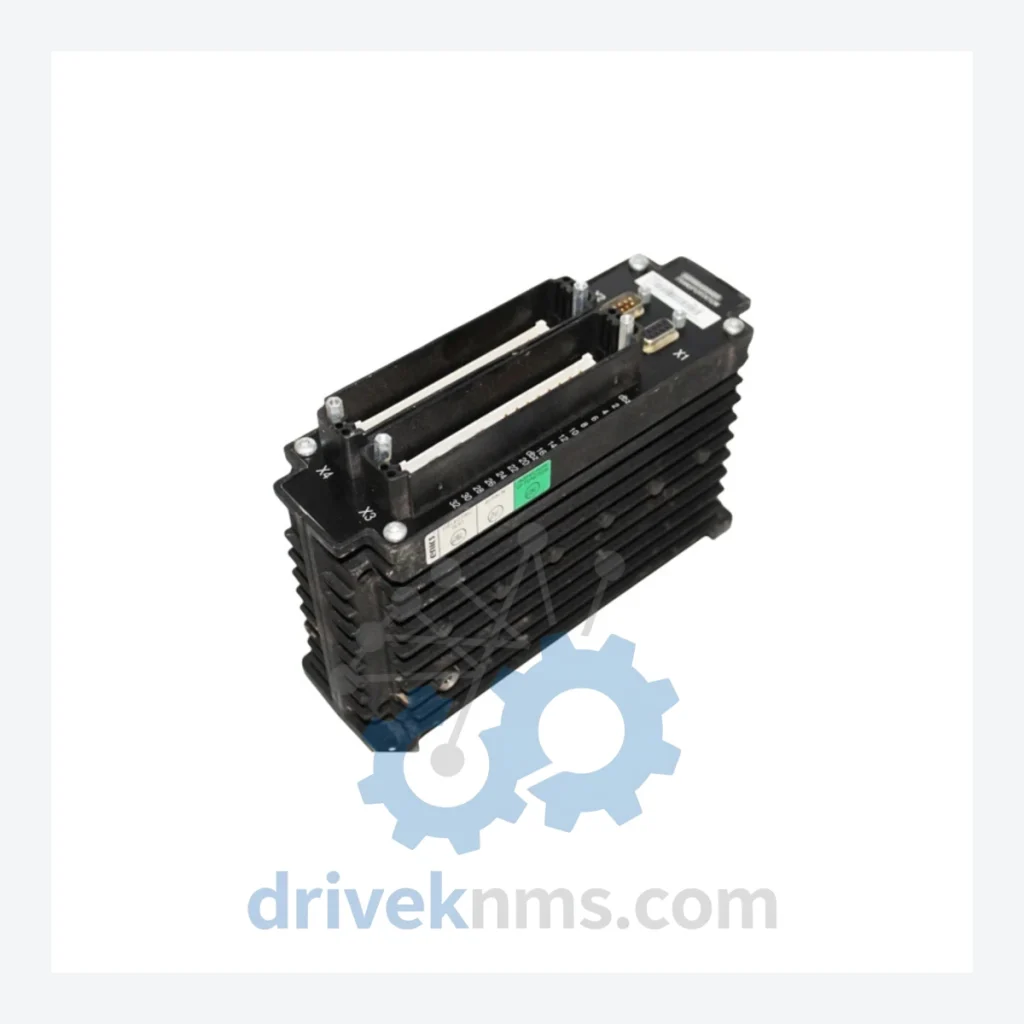
Model: 3EST13-149
Product Overview
Commercial availability is handled through direct RFQ, model verification and export-oriented follow-up rather than public cart checkout.
Datasheet Preview
Use attached product manuals when available. If the manual is not public yet, request the full file directly through RFQ.
Commercial Path
Product pages on DRIVEKNMS are designed to verify model, brand and series first, then move the buyer into one clean quotation path.
Technical Dossier
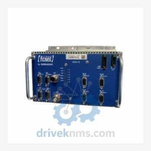
The Bombardier 3EST series represents a critical tier of modular control electronics deployed across global rail transit infrastructure, including metro systems, light rail vehicles (LRV), and mainline traction control platforms. These modules are embedded in Bombardier's MITRAC and INTERFLO control architectures, which have accumulated decades of field installation in high-demand environments: urban metro networks in Europe and Asia, commuter rail corridors in North America, and heavy-haul freight traction systems. The 3EST designation identifies a family of printed circuit board assemblies (PCBAs) and sub-assemblies used for traction inverter control, auxiliary power unit (APU) regulation, door control logic, and vehicle communication bus interfacing. Their role in safety-critical subsystems means that obsolescence management and verified spare parts sourcing are operational priorities for fleet maintenance engineers and rolling stock OEM service teams.
The 3EST series emerged from Bombardier Transportation's modular electronics standardization programs of the late 1990s and early 2000s, designed to replace proprietary single-board designs with interchangeable, rack-mounted PCBAs. Early variants were built around 16-bit microcontroller architectures with parallel backplane buses, conforming to VMEbus and proprietary Bombardier internal bus standards. Mid-generation revisions introduced CAN bus and MVB (Multifunction Vehicle Bus) interfaces per IEC 61375, enabling integration with train-level communication networks (TCN). Later revisions incorporated FPGA-based logic for real-time traction control feedback loops, replacing discrete gate arrays. Compatibility across generations is constrained by backplane connector pinout revisions and firmware dependency chains — a 3EST13-series board is not directly interchangeable with a 3EST10-series board without verifying the hardware revision index and associated software baseline. Boards produced before 2008 may use components now classified as COTS-obsolete (e.g., specific Motorola/Freescale MCUs), requiring either new-old-stock (NOS) sourcing or approved equivalent substitution under the original equipment manufacturer's engineering change order (ECO) process.
The following SKUs represent verified part numbers within the Bombardier 3EST series, classified by primary function. Each entry reflects the module's role within the vehicle control architecture:
3EST13-149: Traction control interface module; primary SKU for inverter gate drive signal conditioning.
3EST13-150: Traction control interface module, revision B; updated overcurrent protection threshold.
3EST13-151: Auxiliary power regulation board; 24 VDC bus monitoring and load switching.
3EST13-152: Auxiliary power regulation board, extended temperature variant (-40°C to +85°C).
3EST14-188: Door control logic module; handles open/close command sequencing and obstruction detection.
3EST14-189: Door control logic module with MVB interface; integrates door status into TCN.
3EST14-190: Door control module, high-current output variant for pneumatic actuator drive.
3EST10-030: Digital input module (DI); 32-channel, 24 VDC, optically isolated.
3EST10-031: Digital input module (DI); 16-channel, 110 VDC, rail-rated surge protection.
3EST10-032: Digital output module (DO); 16-channel, relay output, 5A per channel.
3EST10-033: Digital output module (DO); 32-channel, transistor output, 0.5A per channel.
3EST10-262: Analog input module (AI); 8-channel, ±10 V / 4–20 mA, 12-bit resolution.
3EST10-263: Analog input module (AI); 16-channel, differential input, 16-bit resolution.
3EST10-264: Analog output module (AO); 4-channel, 0–10 V / 4–20 mA, isolated.
3EST10-265: Analog output module (AO); 8-channel, high-precision, ±0.1% full-scale accuracy.
3EST10-266: Communication adapter; CAN bus / MVB dual-port gateway module.
The Bombardier 3EST series has entered the mature-to-declining phase of its product lifecycle. Bombardier Transportation's rail division was acquired by Alstom in January 2021, and the successor entity does not guarantee long-term spare parts supply for legacy 3EST PCBAs. Fleet operators running vehicles with 3EST-based control systems — particularly those with 15+ year service histories — face increasing lead times from OEM channels and are subject to minimum order quantity (MOQ) constraints that are impractical for single-board replacement scenarios.
DriveKNMS maintains a dedicated inventory program for Bombardier 3EST series modules. Stock is sourced through controlled decommissioning of retired rolling stock, authorized surplus channels, and long-term storage agreements with regional rail operators. All units are catalogued by part number, hardware revision, and date code. For operators requiring long-term maintenance agreements (LTMAs) covering 3EST module supply over a 5–10 year horizon, DriveKNMS provides contractual stock reservation and condition-based replenishment scheduling.
3EST series modules present specific test challenges due to their multi-layer PCB construction, mixed-signal analog/digital circuits, and backplane-dependent initialization sequences. DriveKNMS applies the following test protocol to all 3EST units processed through its facility:
Visual and mechanical inspection: Component-level examination under 10× magnification; solder joint integrity assessment per IPC-A-610 Class 3 criteria; connector pin inspection for fretting corrosion and mechanical deformation. Powered functional test: Each board is energized using a dedicated 3EST backplane test fixture that replicates the original rack environment, including bus termination and power sequencing. Input/output channels are exercised across their full specified range. Communication bus verification: CAN and MVB interfaces are tested using protocol analyzers to confirm frame timing, error handling, and node addressing compliance per IEC 61375-3-3. Thermal cycling: Boards are subjected to a minimum of 10 thermal cycles between 0°C and 70°C to identify latent solder joint failures and component parameter drift. Final burn-in: 48-hour powered soak at 55°C ambient with continuous I/O cycling. Units that pass all stages are issued a DriveKNMS test certificate with individual serial number traceability.
© 2026 DriveKNMS. All trademarks belong to their respective owners. Specifications are for reference only and subject to change without notice. Verify all parameters against official documentation before installation.
Related Paths
Bombardier 3EST Series: Comprehensive Module Range and Technical Overview The Bombardier 3EST series represents a core family of input/output and…
Bombardier DCC Series: Comprehensive Module Range and Technical Overview The Bombardier DCC (Drive Control Card) series represents a core control…
Bombardier 3EST27-99 Transmission Interface Module: Global Sourcing Strategy & Asset Return Value The Bombardier 3EST27-99 Transmission Interface Module is a…