
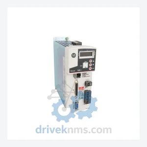
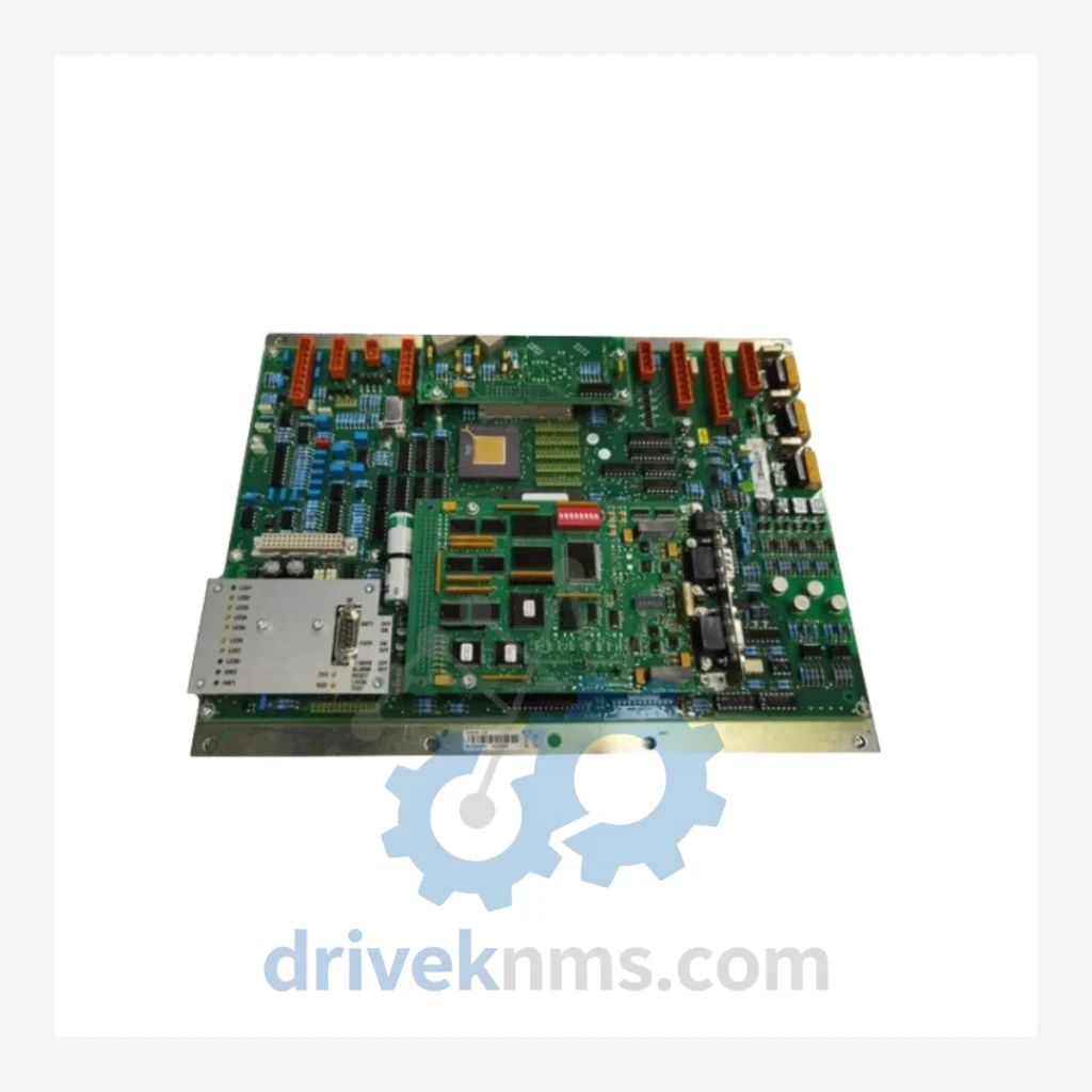
Bombardier DCC Series Modules DCC2223A 3EST125-977 Drive Control Unit
Bombardier DCC2223A 3EST125-977 is listed for Servo Drives RFQ review. Confirm quantity, condition and destination before quotation.
RFQ-ready industrial model
Model: DCC2390A 3EST49-116 DTCC901B
Product Overview
Commercial availability is handled through direct RFQ, model verification and export-oriented follow-up rather than public cart checkout.
Datasheet Preview
Use attached product manuals when available. If the manual is not public yet, request the full file directly through RFQ.
Commercial Path
Product pages on DRIVEKNMS are designed to verify model, brand and series first, then move the buyer into one clean quotation path.
Technical Dossier
The DTCC901B lineage traces its origins to Bombardier's early digital drive controller platforms developed in the late 1980s. The first-generation units relied on discrete analog signal conditioning with limited digital feedback loops. By the mid-1990s, the architecture transitioned to fully digital PWM (Pulse Width Modulation) control with integrated fault diagnostics, culminating in the DCC2390A sub-series. The 3EST49-116 board revision introduced enhanced EMI shielding, revised gate-driver circuitry, and expanded parameter memory to support multi-motor topologies.
Compatibility considerations are critical for maintenance engineers: early DTCC901B variants use a proprietary 96-pin DIN backplane connector that is not forward-compatible with later VME-based racks. Firmware versions prior to V4.x require a dedicated programming interface (Bombardier PGM-200 or equivalent) and are not accessible via standard RS-485 tools. Engineers sourcing replacement units must verify the board revision suffix (e.g., -116) to ensure electrical and firmware compatibility with the host drive chassis.
As of 2026, the DTCC901B series is classified as End-of-Life (EOL) by Bombardier's successor entities. No new production runs are planned. Long-term maintenance support is available exclusively through authorized aftermarket distributors and specialist spare-parts suppliers.
The following SKUs represent verified, commonly sourced modules within the Bombardier DTCC901B drive control ecosystem. Each entry reflects a distinct functional role within the drive system architecture.
DCC2390A 3EST49-116 DTCC901B: Main drive control unit, PWM regulation, fault logging, 96-pin backplane interface.
DCC2390B 3EST49-116 DTCC901B: Revised gate-driver variant with enhanced short-circuit protection and updated EEPROM map.
DCC2391A 3EST49-118 DTCC901B: Extended-temperature version (-40°C to +70°C), designed for outdoor drive enclosures.
DCC2392A 3EST49-120 DTCC901B: Dual-axis control variant supporting master-follower motor configurations.
DCC2393A 3EST49-122 DTCC901B: High-current output module rated for drives above 500A continuous.
DCC2394A 3EST49-124 DTCC901B: Regenerative braking control board with energy-return bus interface.
DCC2395A 3EST49-126 DTCC901B: Analog I/O expansion card, 8x AI / 4x AO, ±10V and 4–20mA selectable.
DCC2396A 3EST49-128 DTCC901B: Digital I/O interface module, 16x DI / 8x DO, 24VDC logic level.
DCC2397A 3EST49-130 DTCC901B: Fieldbus communication adapter, Profibus-DP V1, up to 12Mbit/s.
DCC2398A 3EST49-132 DTCC901B: DeviceNet communication module, Group 2 slave, 500kbit/s.
DCC2399A 3EST49-134 DTCC901B: Modbus RTU/TCP gateway card, dual-port Ethernet + RS-485.
DCC2400A 3EST49-136 DTCC901B: Power supply module, 24VDC/5A regulated output for control electronics.
DCC2401A 3EST49-138 DTCC901B: Encoder feedback interface, incremental/absolute, up to 1024 PPR.
DCC2402A 3EST49-140 DTCC901B: Resolver interface card, 2-pole to 16-pole resolver input, 10kHz excitation.
DCC2403A 3EST49-142 DTCC901B: Diagnostic and parameter memory module, non-volatile FRAM, 512KB.
DCC2404A 3EST49-144 DTCC901B: Redundancy switchover module for hot-standby drive configurations.
DCC2405A 3EST49-146 DTCC901B: Thermal management controller, fan speed regulation, over-temperature trip.
The DTCC901B series presents specific test challenges due to its proprietary backplane bus protocol and multi-layer PCB construction. DriveKNMS applies the following verification procedures to all units prior to dispatch:
Backplane Bus Integrity Test: Each unit is seated in a Bombardier-compatible test rack and subjected to full bus communication cycling at rated speed to verify address decoding and data integrity.
Gate Driver Functional Test: PWM output signals are verified against factory reference waveforms using a calibrated oscilloscope. Rise/fall times and dead-band intervals are measured and logged.
Analog I/O Calibration Check: For I/O expansion variants, all analog channels are verified against a traceable reference standard (±0.1% accuracy).
Thermal Stress Screening: Units are cycled through a 0°C to 55°C thermal profile for a minimum of 4 hours to screen for latent solder joint failures.
Firmware Version Verification: Firmware revision is read and documented. Units with corrupted or mismatched firmware are reflashed using Bombardier-authorized image files where available.
Visual and X-Ray Inspection: High-value units undergo X-ray inspection to detect counterfeit components, re-marked ICs, or substandard solder quality.
Continue The Model Path
Move from this exact model into the matching system hub, brand archive, model-family archive or lifecycle sourcing route before sending a final RFQ list.
Related Paths
Bombardier DCC2223A 3EST125-977 is listed for Servo Drives RFQ review. Confirm quantity, condition and destination before quotation.
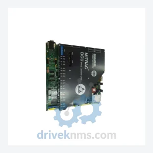
Bombardier DCC2223A is listed for DCC2000 Series RFQ review. Confirm quantity, condition and destination before quotation.
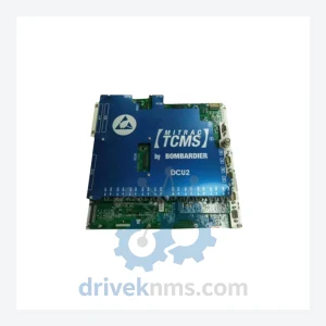
Bombardier DCU2 DCC 2580B is listed for Excitation Series RFQ review. Confirm quantity, condition and destination before quotation.