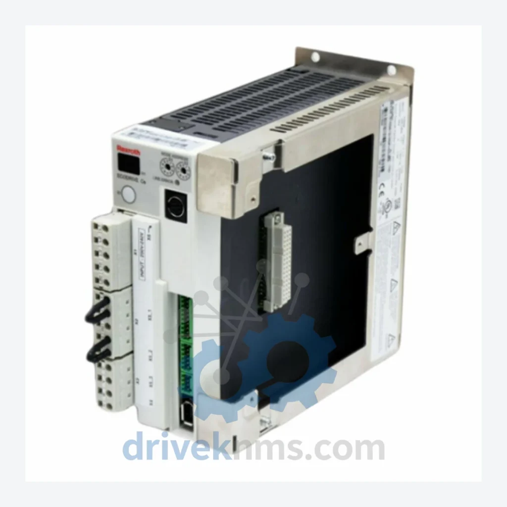
Rexroth DKC Series Modules DKC1.03-008-3-MGP-01VRS

Model: DKC1.03-008-3-MGP-01VRS

Series DKC Series
Model DKC1.03-008-3-MGP-01VRS
RFQ-ready model route Obsolete and surplus sourcing Export follow-up by model list

Product Overview

Commercial availability is handled through direct RFQ, model verification and export-oriented follow-up rather than public cart checkout.

Datasheet Preview

Datasheet Preview

Use attached product manuals when available. If the manual is not public yet, request the full file directly through RFQ.

Request Full Manual

Commercial Path

Use This Page To Confirm The Model, Then Move To RFQ

Product pages on DRIVEKNMS are designed to verify model, brand and series first, then move the buyer into one clean quotation path.

Technical Dossier

Product Details And Specifications

Bosch Rexroth DKC Series Technical Notes

The Evolution of DKC Series Architecture

The DKC series was introduced as part of Rexroth's DIAX04 drive system, succeeding the earlier DIAX03 (DKC03) platform. The architecture is built around a common power bus (DC link) with modular firmware plug-in cards (FWA-DIAX04-xxx) that define the drive's operational profile — whether positioning, speed, torque, or synchronization. Communication is handled via interchangeable interface modules supporting SERCOS I (fiber optic ring), PROFIBUS-DP, DeviceNet, Interbus, and CANopen, allowing the same power hardware to integrate into virtually any PLC or DCS environment without hardware replacement.

The DKC1.x sub-family targets single-axis applications in the 2.5 A to 100 A continuous current range. The DKC2.x sub-family introduced enhanced multi-axis synchronization. The DKC3.x line added expanded memory and higher-resolution encoder interfaces. Firmware versioning (e.g., MGP-01VRS, EFC-01VRS, FLP-01VRS) is critical: firmware is not universally interchangeable across hardware revisions, and mismatched firmware-hardware combinations will result in F8xxx fault codes at startup. As of 2026, the DKC series has entered end-of-life status with Bosch Rexroth, with IndraDrive (HCS, HMS, HMD) designated as the modern replacement platform. However, the installed base remains large enough that OEM-equivalent spare parts and refurbished units remain commercially essential.

DKC Series Full Catalog & Functionalities (SKU List)

The following SKUs represent verified, commonly stocked models within the Rexroth DKC / DIAX04 ecosystem, organized by functional category:

Servo Drive Controllers — DKC1.x (Single-Axis, Standard Current Range)

  • DKC1.03-008-3-MGP-01VRS: Single-axis servo drive, 8 A continuous, 3-phase 400 V AC input, MGP positioning firmware, SERCOS interface ready.
  • DKC1.03-012-3-MGP-01VRS: Single-axis servo drive, 12 A continuous, 400 V, MGP firmware, standard DIAX04 backplane compatible.
  • DKC1.03-018-3-MGP-01VRS: Single-axis servo drive, 18 A continuous, 400 V, MGP firmware, suitable for mid-torque servo axes.
  • DKC1.03-040-3-MGP-01VRS: Single-axis servo drive, 40 A continuous, 400 V, MGP firmware, high-current axis applications.
  • DKC1.03-100-3-MGP-01VRS: Single-axis servo drive, 100 A continuous, 400 V, MGP firmware, heavy-duty spindle and feed axis use.
  • DKC1.03-008-3-FLP-01VRS: Single-axis servo drive, 8 A, FLP (electronic gearing / cam) firmware variant for synchronization applications.
  • DKC1.03-018-3-EFC-01VRS: Single-axis servo drive, 18 A, EFC (electronic cam) firmware, used in packaging and printing machinery.

Servo Drive Controllers — DKC2.x (Enhanced Synchronization)

  • DKC2.1-040-7-FW: Dual-axis capable controller, 40 A, 700 V DC bus, firmware-configurable, used in coordinated multi-axis gantry systems.
  • DKC2.3-040-7-FW: Updated DKC2 revision, 40 A, 700 V, enhanced encoder interface, compatible with Heidenhain EnDat 2.1.
  • DKC2.3-100-7-FW: High-current DKC2 variant, 100 A, 700 V DC bus, heavy-duty coordinated axis control.

Servo Drive Controllers — DKC3.x (Extended Memory / High-Resolution Encoder)

  • DKC3.1-040-7-FW: DKC3 platform, 40 A, 700 V, extended program memory, supports EnDat 2.2 and Hiperface encoders.
  • DKC3.3-040-7-FW: Revised DKC3, 40 A, enhanced diagnostic memory, compatible with SERCOS II.
  • DKC3.3-100-7-FW: High-current DKC3, 100 A, 700 V, full EnDat 2.2 support, used in precision grinding and milling centers.

Communication Interface Modules (Plug-in, DKC-compatible)

  • CSB01.1N-SE-ENS-NNN-NN-S-NN-FW: SERCOS I fiber optic interface module for DKC1/DKC2/DKC3 drives, 2 Mbit/s and 4 Mbit/s selectable ring speed.
  • CSB01.1N-PB-ENS-NNN-NN-S-NN-FW: PROFIBUS-DP interface module, supports DP-V0 and DP-V1, plug-in replacement for SERCOS module without drive hardware change.
  • CSB01.1N-DN-ENS-NNN-NN-S-NN-FW: DeviceNet interface module for DKC series, Group 2 slave, 125/250/500 kbit/s.

Power Supply / Regenerative Units (DKC System-Compatible)

  • HVR02.2-W018N: Rexroth regenerative power supply unit, 18 kW, compatible with DKC DC bus architecture, feeds shared DC link for multi-axis DKC installations.
  • HVE02.2-W018N: Non-regenerative (resistor braking) supply unit, 18 kW, lower-cost alternative for applications without regenerative energy recovery requirements.

Quality Control for the DKC Series Range

DKC series drives present specific failure modes that require targeted test procedures beyond standard power-on verification. DriveKNMS applies the following protocol to all DKC units prior to dispatch:

  • DC Bus Capacitor ESR Test: Electrolytic capacitors in the DC link section are measured for equivalent series resistance (ESR) and capacitance retention. Units with ESR deviation >20% from nominal are recapped before sale.
  • SERCOS Ring Integrity Test: Fiber optic transmitter/receiver pairs are tested at both 2 Mbit/s and 4 Mbit/s ring speeds using a loopback fixture to confirm optical power margin.
  • Firmware-Hardware Compatibility Verification: Each unit's installed firmware version (readable via the drive's H1 diagnostic display) is logged and cross-referenced against Rexroth's firmware compatibility matrix to confirm the hardware revision supports the installed FWA version.
  • Encoder Interface Functional Test: Resolver, TTL incremental, and EnDat encoder interfaces are exercised using a signal simulator to confirm correct position feedback processing and absence of F2xxx encoder fault codes.
  • Thermal Cycling Burn-In: Units are operated under load at elevated ambient temperature (50°C) for a minimum of 4 hours to screen for latent component failures before dispatch review.

Continue The Model Path

Use system, brand and series routes to compare related published models.

Move from this exact model into the matching system hub, brand archive, model-family archive or lifecycle sourcing route before sending a final RFQ list.

WhatsApp Prefilled Inquiry Email sale@driveknms.com Phone +86 18359293191 Top Back To Top