
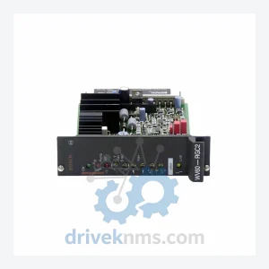
Bosch Rexroth WV60-RGC2
Bosch Rexroth WV60-RGC2 is listed for Monitoring Systems RFQ review. Confirm quantity, condition and destination before quotation.
RFQ-ready industrial model
Model: DM-51
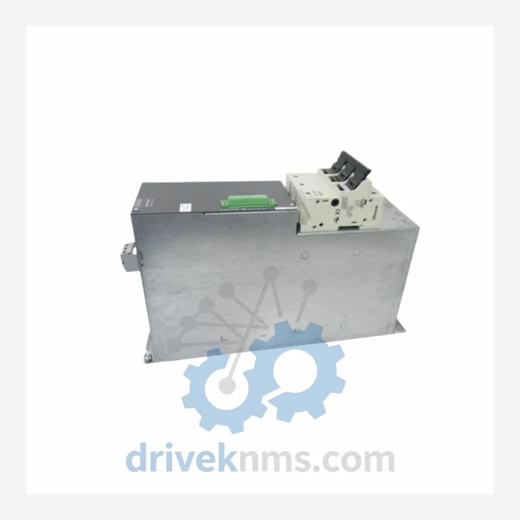
Product Overview
Commercial availability is handled through direct RFQ, model verification and export-oriented follow-up rather than public cart checkout.
Datasheet Preview
Use attached product manuals when available. If the manual is not public yet, request the full file directly through RFQ.
Commercial Path
Product pages on DRIVEKNMS are designed to verify model, brand and series first, then move the buyer into one clean quotation path.
Technical Dossier
The Rexroth DM Series was introduced as part of the DIAX02 and DIAX03 drive platform generations, succeeding earlier analog servo amplifier families. Early DM variants operated on ±10V analog command interfaces with resolver feedback. Subsequent revisions integrated SERCOS I fiber-optic communication, enabling deterministic real-time motion coordination across multi-axis CNC and robotics installations. The DM-51 belongs to the mid-generation DIAX03 platform, characterized by its modular power section, onboard parameter memory (E²PROM), and compatibility with Rexroth IndraControl L and V controller families. As the platform matured, Rexroth transitioned customers toward the IndraDrive C (HCS) and IndraDrive M (HMS/HMD) families, which offer EtherCAT and PROFINET connectivity. However, DM Series drives remain in active service in facilities where full drive-train replacement is cost-prohibitive, making long-term spare parts availability a critical operational requirement. Firmware compatibility between DM generations requires careful cross-referencing of parameter sets (P-0-xxxx) to avoid axis tuning regression during unit substitution.
The following SKUs represent verified models within the Rexroth DM Series drive family, organized by functional classification:
Single-Axis Servo Amplifiers (Compact Class)
Dual-Axis and Multi-Axis Configurations
Power Supply and Bus Modules
Feedback and Communication Modules
Each DM Series unit processed by DriveKNMS undergoes a structured multi-stage verification protocol designed specifically for the DIAX03 drive platform architecture. Stage 1 — Visual and Mechanical Inspection: examination of power terminals, fiber-optic ports, plug-in card connectors, and capacitor condition. Stage 2 — DC Bus Energization: controlled ramp-up via variac to rated DC bus voltage (560–650 VDC for 400V class units) with leakage current monitoring. Stage 3 — Functional Drive Test: the unit is connected to a matched Rexroth MKD or MHD test motor and commanded through full velocity and torque loop operation via SERCOS or analog interface. Stage 4 — Thermal Soak: continuous operation at 80% rated current for 2 hours with thermal imaging to identify failing IGBTs or gate driver degradation. Stage 5 — Parameter Verification: all factory default parameters are confirmed against the Rexroth DM Series parameter reference manual. Units that pass all five stages are issued a DriveKNMS test certificate with date stamp, technician ID, and measured performance data.
Continue The Model Path
Move from this exact model into the matching system hub, brand archive, model-family archive or lifecycle sourcing route before sending a final RFQ list.
Related Paths
Bosch Rexroth WV60-RGC2 is listed for Monitoring Systems RFQ review. Confirm quantity, condition and destination before quotation.
Bosch Rexroth 3402062000 640-34020619XD-1FA 640-34020619XD-2FA is listed for Indramat RFQ review. Confirm quantity, condition and destination before quotation.
Bosch Rexroth R911170436 is listed for IndraDrive RFQ review. Confirm quantity, condition and destination before quotation.