
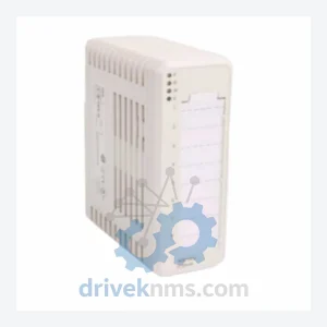
Rexroth VT-HNC100.C-30/P-S-00/000 Digital Axis Controller – VT-HNC100 Series
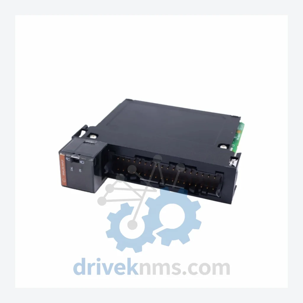
Bosch Rexroth AO810V2 3BSE038415R1 is listed for VT-HNC100 Series RFQ review. Confirm quantity, condition and destination before quotation.
RFQ-ready industrial model
Model: BT-EN-MB2-P
Product Overview
Commercial availability is handled through direct RFQ, model verification and export-oriented follow-up rather than public cart checkout.
Datasheet Preview
Use attached product manuals when available. If the manual is not public yet, request the full file directly through RFQ.
Commercial Path
Product pages on DRIVEKNMS are designed to verify model, brand and series first, then move the buyer into one clean quotation path.
Technical Dossier
The Bosch Rexroth IndraDrive series represents one of the most widely deployed servo drive platforms in global heavy industry. Installed across petrochemical refineries, automotive body-in-white lines, steel rolling mills, paper processing plants, and nuclear facility auxiliary systems, IndraDrive hardware forms the motion control backbone of production assets with operational lifespans measured in decades. The BT-EN-MB2-P is a PROFIBUS DP communication option module for IndraDrive C and IndraDrive M drive controllers, enabling fieldbus integration into distributed control architectures. Its continued presence in active production environments — long after Bosch Rexroth has shifted commercial focus toward IndraDrive Mi and ctrlX DRIVE — makes sourcing of this module a recurring operational necessity for maintenance engineers worldwide.
Bosch Rexroth's drive platform evolution spans four distinct generations, each introducing architectural changes that created compatibility boundaries still relevant to maintenance planning today.
The Indramat TDM/KDV era (1980s–mid-1990s) established the foundation: analog command interface drives paired with DKC power supplies, controlled via proprietary Indramat fieldbus. These units are fully discontinued and require specialized sourcing for any replacement component.
The ECODRIVE / DKC series (mid-1990s–2003) introduced digital SERCOS I interface and early PROFIBUS support. DKC01, DKC02, and DKC03 variants remain in service in many European and Asian manufacturing facilities. Firmware versions are hardware-locked, making module-level replacement the only viable repair path when drive intelligence fails.
The IndraDrive C / IndraDrive M generation (2003–2015) — the platform to which BT-EN-MB2-P belongs — standardized the option module slot architecture. Communication, safety, and I/O expansion were handled through interchangeable option cards inserted into defined slots (S1, S2, S3). This modularity was a maintenance advantage during active production but now creates sourcing complexity as individual option modules age out of distribution channels.
The following SKUs represent verified components within the Bosch Rexroth IndraDrive C, IndraDrive M, and related Indramat legacy platforms. Each entry reflects a distinct functional role within the drive system architecture.
Communication Option Modules (PROFIBUS / SERCOS / EtherNet)
IndraDrive C Drive Controllers (HCS Series)
IndraDrive M Power Supply Units (HMV Series)
IndraDrive M Axis Modules (HMD / HMS Series)
Legacy Indramat / ECODRIVE (DKC Series)
IndraDrive option modules present specific failure modes that require targeted inspection protocols. Standard visual inspection is insufficient for fieldbus communication modules, where internal component degradation may not produce visible indicators.
DriveKNMS applies the following verification process to all IndraDrive C/M option modules prior to dispatch:
Continue The Model Path
Move from this exact model into the matching system hub, brand archive, model-family archive or lifecycle sourcing route before sending a final RFQ list.
Related Paths
Bosch Rexroth AO810V2 3BSE038415R1 is listed for VT-HNC100 Series RFQ review. Confirm quantity, condition and destination before quotation.
Bosch Rexroth REXROTH VT-HACD-1-12/V0/1-0-0 R978005518 Controller Card is listed for Amplifier Series RFQ review. Confirm quantity, condition and destination before quotation.
Bosch Rexroth DKC03.3-040-7-FW is listed for DKC Series RFQ review. Confirm quantity, condition and destination before quotation.