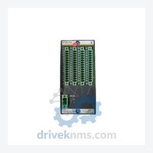
DAIHEN FLB-60M-03 0190-19674 Control Board – Obsolete OTC Series Spare Part
DAIHEN FLB-60M-03 0190-19674 Control Board – Obsolete OTC Series Spare Part When a control board fails in a DAIHEN welding…
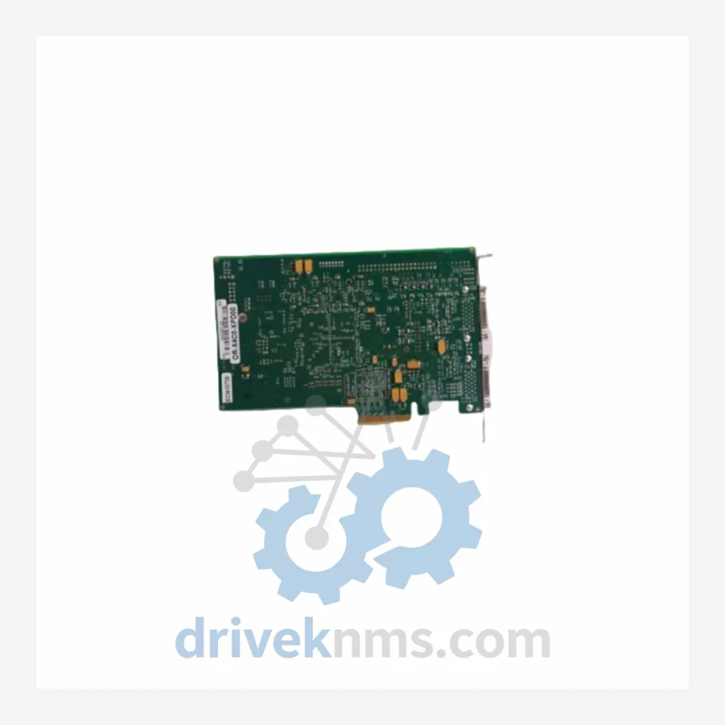
Model: UM356B PART NO L21700M(L21700M03) PCB-I-E-1171
Product Overview
Commercial availability is handled through direct RFQ, model verification and export-oriented follow-up rather than public cart checkout.
Datasheet Preview
Use attached product manuals when available. If the manual is not public yet, request the full file directly through RFQ.
Commercial Path
Product pages on DRIVEKNMS are designed to verify model, brand and series first, then move the buyer into one clean quotation path.
Technical Dossier
The DAIHEN UM356B series represents a core control and drive platform deployed across global heavy industry sectors, including petrochemical refineries, nuclear power auxiliary systems, steel mill automation lines, and large-scale chemical processing plants. DAIHEN Corporation, headquartered in Osaka, Japan, engineered the UM356B platform to serve as a high-reliability PCB-level control architecture within its inverter welding and industrial drive systems. The UM356B series PC boards are embedded in equipment with operational lifespans exceeding 15–20 years, making long-term spare parts availability a critical procurement concern for maintenance engineers and plant reliability teams worldwide.
The UM356B platform was developed as part of DAIHEN's second-generation inverter control architecture, succeeding earlier UM-series boards that relied on discrete analog control logic. The UM356B introduced hybrid analog-digital signal processing on a single PCB substrate, enabling tighter feedback loop control for IGBT-based inverter stages. Early revisions (suffix variants such as L21700M01 and L21700M02) used through-hole component layouts with DIP ICs. The L21700M03 revision — as found in PCB-I-E-1171 — transitioned to a mixed SMD/through-hole design, improving thermal stability and reducing susceptibility to vibration-induced solder joint failure in high-cycle industrial environments. Compatibility between revision suffixes requires verification against the host unit's firmware version and backplane connector pinout. Cross-revision substitution without engineering review is not recommended in safety-critical applications.
The following SKUs represent verified components within the DAIHEN UM356B and closely associated UM-series control board ecosystem. Each entry reflects a distinct functional role within the inverter drive or welding power supply control architecture.
UM356B PART NO L21700M(L21700M03) PCB-I-E-1171: Main inverter feedback and signal conditioning PC board, mixed SMD/THT, revision 03.
UM356B PART NO L21700M(L21700M01) PCB-I-E-1171: Early revision, full through-hole layout; functionally equivalent with pinout verification required.
UM356B PART NO L21700M(L21700M02) PCB-I-E-1171: Intermediate revision; DIP-to-SMD transition variant for select drive frame sizes.
UM356B PCB-I-E-1172: Gate drive interface board; interfaces IGBT modules to main control logic layer.
UM356B PCB-I-E-1173: Overcurrent and overvoltage protection logic board; hardwired fault latch circuit.
UM356B PCB-I-E-1174: Auxiliary power supply regulation board; generates +5V/±15V rails for control electronics.
UM356B PCB-I-E-1175: Current transformer signal processing board; hall-effect sensor interface for output current feedback.
UM356B PCB-I-E-1176: Communication interface board; RS-485 serial link to operator panel or PLC host.
UM356B PCB-I-E-1177: Temperature monitoring and fan control board; NTC thermistor input, PWM fan output.
UM356B PCB-I-E-1178: Arc start and wire feed sequencing control board; used in MIG/MAG welding power supply variants.
UM356B PCB-I-E-1179: Waveform shaping and pulse parameter board; configures output waveform for pulsed GMAW processes.
UM356B PCB-I-E-1180: Display driver and keypad interface board; 7-segment LED output, membrane keypad input.
UM356B PCB-I-E-1181: Analog reference and calibration board; precision voltage reference for ADC zero/span calibration.
UM356B PCB-I-E-1182: Soft-start and inrush current limiting board; controls pre-charge relay sequencing on DC bus.
UM356B PCB-I-E-1183: Isolation amplifier board; galvanic isolation between high-voltage inverter stage and low-voltage control logic.
UM356B PCB-I-E-1184: Fieldbus expansion board; optional PROFIBUS-DP or DeviceNet adapter for plant-level integration.
The DAIHEN UM356B series has entered the mature-to-end-of-life phase of its product lifecycle. DAIHEN's official parts support for early revision boards (L21700M01, L21700M02) has been discontinued in most markets. DriveKNMS maintains a dedicated inventory of tested UM356B PC boards sourced through authorized secondary market channels, decommissioned equipment buybacks, and verified OEM surplus. For plant operators running DAIHEN inverter systems with no planned capital replacement within the next 5–10 years, DriveKNMS provides lifecycle extension support including: board-level repair assessment, functional equivalency cross-referencing between revision suffixes, and consignment stocking agreements for high-volume maintenance contracts. All sourced boards are individually serialized and traceable to their procurement origin.
UM356B PC boards undergo a structured incoming inspection and functional verification protocol at DriveKNMS before dispatch. The process includes: visual inspection under 10× magnification for solder joint integrity, component presence, and PCB trace condition; in-circuit resistance mapping against reference values for known-good boards; powered bench test using a controlled DC bus simulator to verify auxiliary power rail outputs (+5V, ±15V) within ±2% tolerance; signal injection testing on feedback input channels to confirm ADC linearity and fault latch response; and final isolation resistance test (>100MΩ at 500VDC) between high-voltage and low-voltage circuit domains. Boards that fail any stage are quarantined and documented. No board is dispatched without a passed test record.
Related Paths
DAIHEN FLB-60M-03 0190-19674 Control Board – Obsolete OTC Series Spare Part When a control board fails in a DAIHEN welding…
ALSTOM MVAJ105RA0802A Protection Relay: Supply Continuity Strategy for a Discontinued Critical Component The ALSTOM MVAJ105RA0802A is a numerical protection relay…
MOORE 16137 Series: Comprehensive Module Range and Technical Overview The MOORE 16137 Series represents a core component family within Moore…