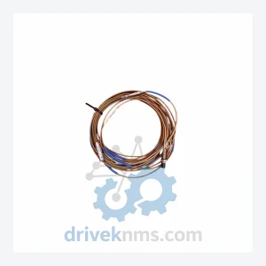
EPRO PR6423/003-030-CN CON021 Vibration Sensor – Obsolete PR6423 Series Spare Part
EPRO PR6423/003-030-CN CON021 Vibration Sensor – Obsolete PR6423 Series Spare Part When a vibration monitoring channel fails on a turbine,…
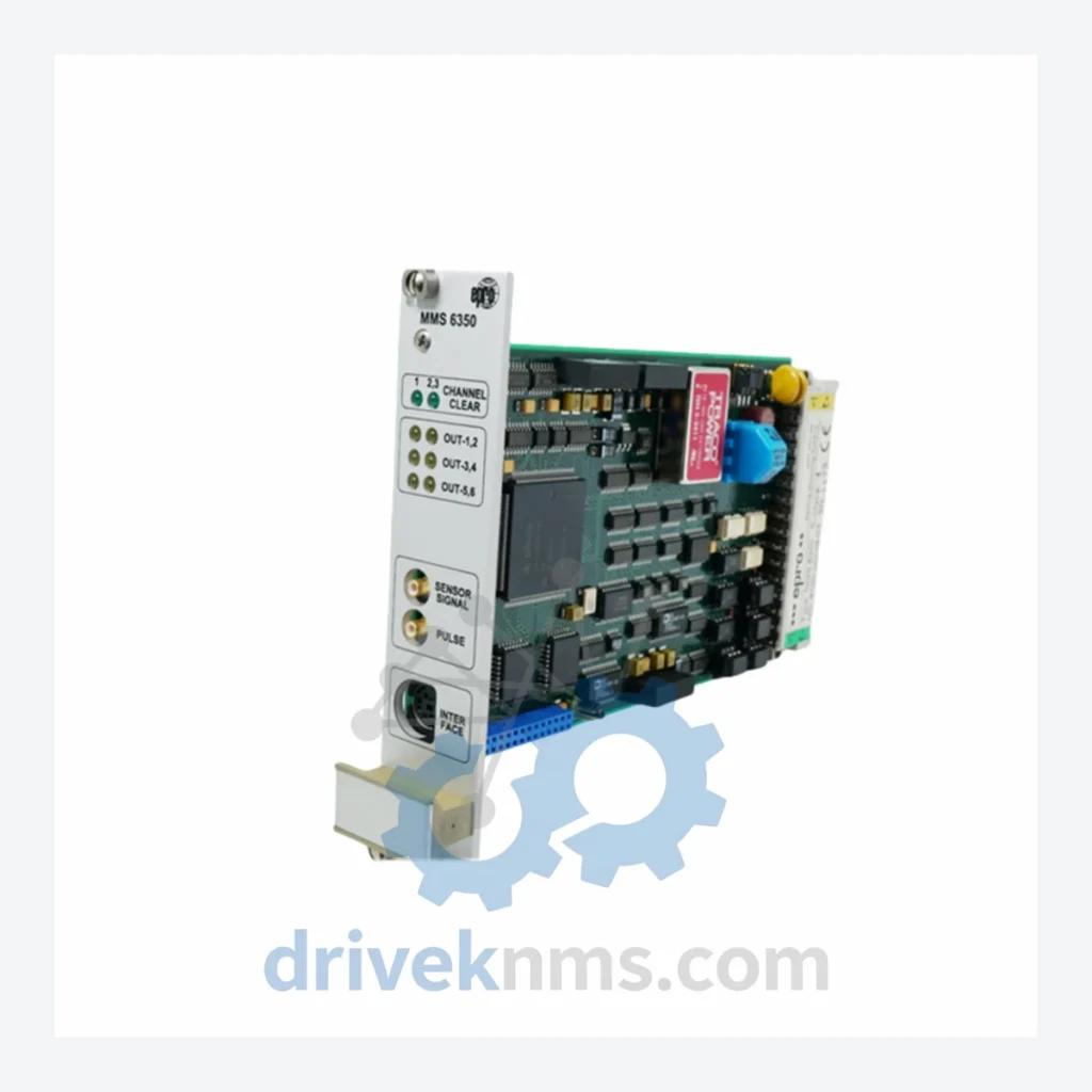
Model: MMS6350/DP
Product Overview
Commercial availability is handled through direct RFQ, model verification and export-oriented follow-up rather than public cart checkout.
Datasheet Preview
Use attached product manuals when available. If the manual is not public yet, request the full file directly through RFQ.
Commercial Path
Product pages on DRIVEKNMS are designed to verify model, brand and series first, then move the buyer into one clean quotation path.
Technical Dossier
The EPRO MMS6350 series is a dedicated line of digital overspeed protection systems engineered for critical rotating machinery in heavy industrial environments. Deployed extensively in petrochemical plants, nuclear power stations, offshore platforms, and oil refineries, the MMS6350 series provides turbine, compressor, and pump shaft overspeed detection with trip-relay outputs conforming to SIL 2 / IEC 61508 functional safety requirements. The series is manufactured by EPRO GmbH (a Metso Automation / Baker Hughes company) and represents the digital successor to the earlier MMS3000 and MMS6000 analog protection families. Its modular rack-based architecture allows integration into existing DCS/SIS backplanes without full system replacement, making it a preferred choice for brownfield lifecycle extension projects across the global process industry.
EPRO's machine protection portfolio evolved through three distinct generations. The first generation (MMS3000 series, 1980s–1990s) relied on analog signal conditioning with discrete relay logic, offering limited diagnostic transparency and no digital fieldbus connectivity. The second generation (MMS6000 series, mid-1990s to early 2000s) introduced microprocessor-based signal processing and RS-485 serial communication, enabling basic SCADA integration but still constrained by proprietary protocol stacks.
The MMS6350 series (introduced circa 2005) represents the third generation: fully digital, with on-board DSP for real-time frequency measurement, configurable trip thresholds via software, and support for Modbus RTU / Profibus DP fieldbus protocols. The MMS6350/DP variant specifically integrates a Profibus DP communication interface, enabling direct integration into Siemens PCS 7, ABB 800xA, and Honeywell Experion DCS environments. Backward compatibility with MMS6000-series sensor wiring (eddy-current probes, magnetic pickups) was preserved, reducing retrofit costs. As of 2024, the MMS6350 series has entered the mature/end-of-active-production phase; EPRO continues to supply spare modules through authorized channels, and third-party MRO suppliers such as DriveKNMS provide lifecycle extension support for installed bases.
The following SKUs represent the verified MMS6350 series module range, classified by functional category. Each model is a discrete, field-replaceable unit designed for 19-inch rack or DIN-rail mounting.
Overspeed Protection Modules
Signal Conditioning & Input Modules
Communication & Gateway Modules
Power Supply Modules
CPU & Rack Infrastructure
The MMS6350 series presents specific test challenges due to its integrated backplane communication bus, DSP-based frequency measurement core, and SIL 2 trip relay circuits. DriveKNMS applies a structured verification protocol to all MMS6350 units prior to dispatch. Each module undergoes: (1) visual inspection for PCB damage, connector wear, and capacitor condition; (2) powered functional test at rated supply voltage with simulated MPU/eddy-current probe input signals across the full 0–20 kHz measurement range; (3) trip relay output verification at configured threshold setpoints; (4) fieldbus communication test (Profibus DP or Modbus RTU as applicable) confirming correct node addressing, cyclic data exchange, and diagnostic telegram response; (5) 48-hour burn-in soak at 40°C ambient to screen for latent component failures. Test records are retained for 5 years and are available to customers as part of the quality documentation package.
Related Paths
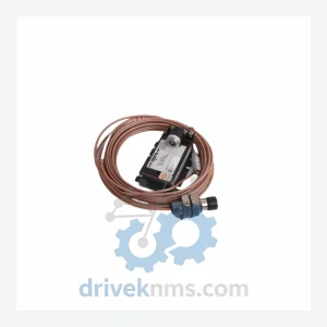
EPRO PR6423/003-030-CN CON021 Vibration Sensor – Obsolete PR6423 Series Spare Part When a vibration monitoring channel fails on a turbine,…
EPRO PR6400 Series: Comprehensive Module Range and Technical Overview The EPRO PR6400 series is a family of eddy-current displacement measurement…
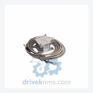
EPRO PR6423 Series: Comprehensive Module Range and Technical Overview The EPRO PR6423 series is a family of eddy-current proximity transducers…