
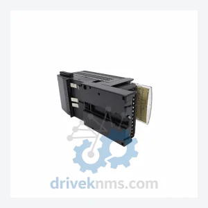
GE IC200ALG431 Analog Mixed I/O Module – VersaMax
GE Fanuc IC200ALG431 is listed for Versamax RFQ review. Confirm quantity, condition and destination before quotation.
RFQ-ready industrial model
Model: IC200ALG630
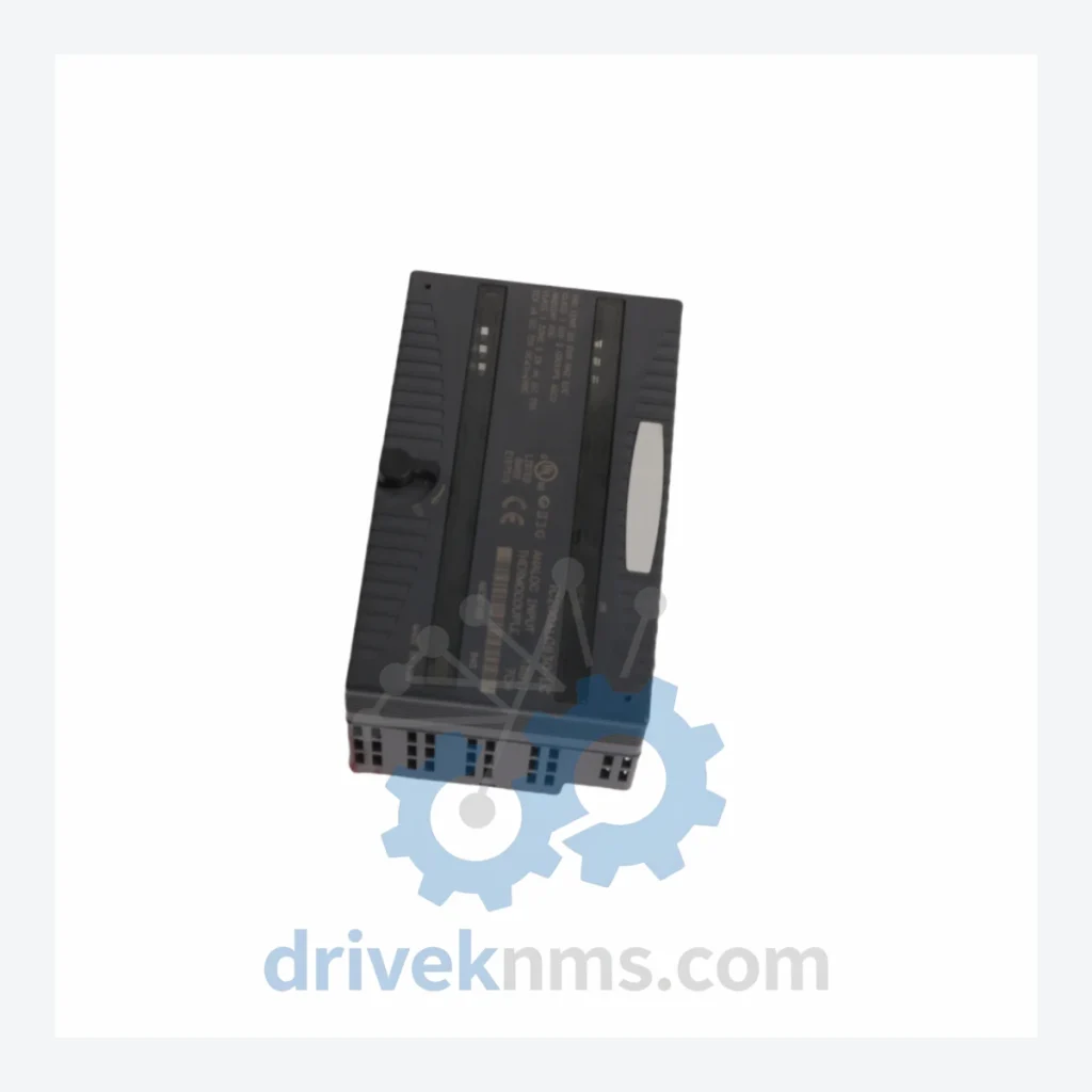
Product Overview
Commercial availability is handled through direct RFQ, model verification and export-oriented follow-up rather than public cart checkout.
Datasheet Preview
Use attached product manuals when available. If the manual is not public yet, request the full file directly through RFQ.
Commercial Path
Product pages on DRIVEKNMS are designed to verify model, brand and series first, then move the buyer into one clean quotation path.
Technical Dossier
The GE Fanuc IC200 series, commercially designated as the VersaMax Micro/Nano platform, is a modular programmable logic controller (PLC) family developed by GE Automation & Controls (formerly GE Fanuc Automation). Deployed across global heavy industry since the mid-1990s, IC200-series hardware is embedded in continuous-process environments including petrochemical refineries, nuclear auxiliary systems, offshore platforms, pulp and paper mills, and municipal water treatment facilities. Its compact backplane architecture, deterministic scan cycle, and broad I/O density made it a default specification in brownfield DCS migration projects throughout the 2000s and 2010s. Installed base estimates place active IC200 nodes in the tens of thousands globally, with a significant proportion operating beyond original design life under extended maintenance contracts.
The IC200 platform was introduced as part of GE Fanuc's VersaMax product line, designed to bridge the gap between micro PLCs and full-rack Series 90-30 systems. Early revisions (circa 1996–2000) established the core backplane bus at 5 VDC logic with RS-485 serial expansion. The IC200CHS series carrier/backplane hardware defined slot-based module addressing that remained backward-compatible through all subsequent firmware generations.
The second architectural phase (2001–2008) introduced Ethernet-capable CPU modules (IC200CPUE05, IC200CPUE05-AE) and expanded the analog I/O density with higher-resolution 16-bit converters. PROFIBUS-DP and DeviceNet adapter modules (IC200BEM103, IC200BEM104) were added to support fieldbus integration in automotive and process plants.
From 2009 onward, GE transitioned active development to the RX3i (IC695) and RX7i (IC698) platforms. The IC200 line entered a maintenance-only phase, with GE issuing end-of-active-development notices for most IC200 CPU and specialty modules between 2012 and 2018. As of 2024, the majority of IC200 catalog numbers are classified as obsolete or last-time-buy, making third-party MRO sourcing the primary procurement channel for ongoing maintenance. Compatibility between IC200 modules and IC200-series CPUs is governed by firmware revision tables; cross-generation substitution requires validation against GE publication GFK-1504.
The following catalog numbers represent verified, commonly stocked IC200-series modules. SKUs are organized by functional category.
Analog Input Modules
Analog Output Modules
Digital Input Modules
Digital Output Modules
CPU Modules
Power Supply Modules
Communication & Network Adapters
IC200 modules present specific test challenges due to their integrated backplane bus architecture and mixed-signal analog circuitry. DriveKNMS applies the following verification protocol to all IC200 inventory prior to dispatch:
Continue The Model Path
Move from this exact model into the matching system hub, brand archive, model-family archive or lifecycle sourcing route before sending a final RFQ list.
Related Paths
GE Fanuc IC200ALG431 is listed for Versamax RFQ review. Confirm quantity, condition and destination before quotation.
GE Fanuc IC200MDD845D is listed for Versamax RFQ review. Confirm quantity, condition and destination before quotation.
GE Fanuc IC670GBI002 is listed for Versamax RFQ review. Confirm quantity, condition and destination before quotation.