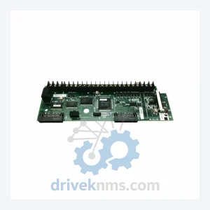
Hitachi 2B021918-1 Circuit Board – Obsolete Hitachi Series Spare Part
Hitachi 2B021918-1 Circuit Board – Obsolete Hitachi Series Spare Part When a circuit board like the Hitachi 2B021918-1 fails in…
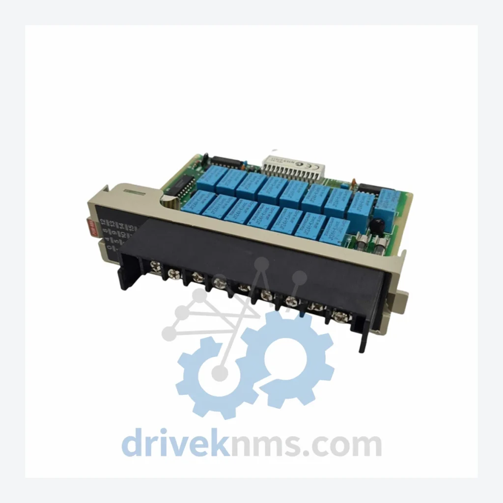
Model: POM-RBH 33029692-1
Product Overview
Commercial availability is handled through direct RFQ, model verification and export-oriented follow-up rather than public cart checkout.
Datasheet Preview
Use attached product manuals when available. If the manual is not public yet, request the full file directly through RFQ.
Commercial Path
Product pages on DRIVEKNMS are designed to verify model, brand and series first, then move the buyer into one clean quotation path.
Technical Dossier
The HITACHI POM-RBH series represents a class of relay control board modules deployed extensively within HITACHI's proprietary Distributed Control System (DCS) and process automation platforms. These boards are installed across global heavy industry sectors including petrochemical refineries, nuclear power generation facilities, chemical processing plants, and large-scale utility infrastructure. The POM-RBH architecture serves as the relay output interface layer between the DCS controller backplane and field-level actuators, providing galvanically isolated switching for critical process control loops. Due to HITACHI's dominant position in Japanese industrial automation and its long-term supply agreements with Asian and Middle Eastern energy operators, POM-RBH boards remain in active service across installations with operational lifespans exceeding 20–30 years.
The POM-RBH series was introduced as part of HITACHI's modular DCS expansion strategy during the late 1980s and early 1990s, designed to standardize relay output interfacing across multiple controller generations. Early revisions of the board utilized through-hole relay components with discrete logic for channel isolation, compatible with HITACHI's EX series and HX series DCS backplanes. Mid-generation revisions introduced surface-mount relay arrays and improved EMI shielding to meet IEC 61000 industrial immunity standards, enabling deployment in high-interference environments such as motor control centers and high-voltage switchgear rooms.
Later production runs of the POM-RBH incorporated enhanced bus communication diagnostics, allowing the host DCS to perform relay coil continuity checks without field intervention. The board's form factor remained backward-compatible across backplane generations, a deliberate design decision by HITACHI to protect long-term plant investments. As HITACHI transitioned its DCS portfolio toward the HISEC and HIACS platforms in the 2000s, the POM-RBH series entered a maintenance-only lifecycle phase. Replacement with modern equivalents requires full I/O mapping validation and in many cases custom adapter brackets, making original spare boards the preferred solution for operating plants.
The following SKUs represent verified models within the HITACHI POM-RBH and closely related relay output board families. Each entry reflects a distinct hardware revision or channel configuration:
POM-RBH 33029692-1: Relay output control board, standard 8-channel configuration, DCS backplane mount
POM-RBH 33029692-2: Relay output control board, revision 2, enhanced contact rating
POM-RBH 33029692-3: Relay output control board, revision 3, improved EMI shielding
POM-RBH 33029693-1: Relay output board, 16-channel variant, dual-row relay array
POM-RBH 33029693-2: 16-channel relay board, revision 2, extended temperature range
POM-RBH 33029694-1: High-density relay output module, 24-channel, compact backplane format
POM-RBH 33029695-1: Relay control board with integrated status LED array per channel
POM-RBH 33029696-1: Isolated relay output board, ATEX-rated variant for hazardous area
POM-RBH 33029697-1: Relay board with manual override switches, maintenance-mode capable
POM-RBH 33029698-1: Relay output board, 24VDC coil voltage, standard DIN rail compatible
POM-RBH 33029699-1: Relay output board, 48VDC coil voltage, substation-grade isolation
POM-RBH 33029700-1: Relay control board, fail-safe de-energize-to-trip configuration
POM-RBH 33029701-1: Relay board, SIL-2 rated variant, safety instrumented system compatible
POM-RBH 33029702-1: Relay output board, high-speed switching, <10ms operate time
POM-RBH 33029703-1: Relay control board, redundant coil driver circuit, hot-standby capable
POM-RBH 33029704-1: Relay output board, conformal-coated PCB, marine and offshore grade
DriveKNMS maintains a dedicated inventory program for HITACHI POM-RBH series boards that have reached end-of-manufacture status. As HITACHI no longer produces replacement boards for legacy DCS platforms, operating plants face a critical supply gap when boards fail during scheduled turnarounds or unplanned outages. DriveKNMS sources POM-RBH boards through a global network of decommissioned plant asset liquidations, authorized surplus distributors, and long-term storage facilities in Japan, Germany, and the United States.
All sourced POM-RBH boards undergo full refurbishment assessment prior to listing. Boards with degraded relay contacts, cracked PCB traces, or failed bus interface ICs are either repaired to OEM specification or removed from inventory. DriveKNMS provides documentation packages including test reports, revision identification, and compatibility cross-reference for each shipped unit. For plants requiring long-term maintenance contracts covering multiple POM-RBH variants, DriveKNMS offers consignment stocking agreements with guaranteed response times.
The POM-RBH board presents specific quality verification challenges due to its relay-based output architecture and backplane bus interface. DriveKNMS applies the following test protocol to each unit:
Relay Coil Resistance Verification: Each relay coil is measured against OEM nominal resistance specifications. Coils outside ±10% tolerance are replaced with equivalent-rated components.
Contact Continuity and Isolation Test: All relay contacts are cycled a minimum of 50 times under rated load. Contact resistance is measured in the closed state; isolation resistance is verified in the open state at 500VDC.
Backplane Bus Communication Test: The board is installed in a HITACHI-compatible test backplane and subjected to full read/write command cycles from a reference controller to verify bus address decoding and response integrity.
Channel-by-Channel Functional Test: Each output channel is individually activated and verified against a reference load bank. Switching time, hold voltage, and dropout voltage are recorded.
Thermal Cycling: Boards are subjected to a 0°C to 55°C thermal cycle to identify cold-solder joints and thermally sensitive component failures before shipment.
Related Paths
Hitachi 2B021918-1 Circuit Board – Obsolete Hitachi Series Spare Part When a circuit board like the Hitachi 2B021918-1 fails in…
Hitachi MVL-D64DT PLC Controller – Obsolete H Series Spare Part When a Hitachi MVL-D64DT fails on the production floor, the…
HITACHI MVH-D40DT Basic Module: Supply Continuity Strategy for Procurement Managers The HITACHI MVH-D40DT is a discontinued basic module from HITACHI's…