KUKA KCP2 VKCP2 Robot Control Panel – KCP Series
KUKA KCP2 VKCP2 Robot Control Panel: Sourcing Strategy & Asset Return Value in a Constrained Global Supply Chain The KUKA…
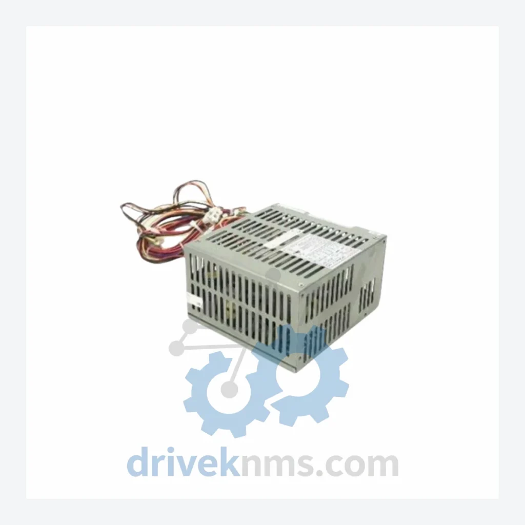
Model: SPS-DY150H 00-105-904
Product Overview
Commercial availability is handled through direct RFQ, model verification and export-oriented follow-up rather than public cart checkout.
Datasheet Preview
Use attached product manuals when available. If the manual is not public yet, request the full file directly through RFQ.
Commercial Path
Product pages on DRIVEKNMS are designed to verify model, brand and series first, then move the buyer into one clean quotation path.
Technical Dossier
The KUKA SPS-DY150H series is a dedicated power supply platform engineered for KUKA robot controller cabinets, with primary deployment across heavy industrial environments including automotive body-in-white lines, chemical processing plants, nuclear facility handling systems, and petroleum refinery automation cells. The SPS-DY150H designation identifies a regulated DC power supply module designed to deliver stable low-voltage rails to the controller backplane, I/O racks, and communication interfaces within KUKA KRC (KUKA Robot Controller) generations. Installed base figures place this series among the most widely distributed controller power components in European and Asian manufacturing facilities, with documented deployments spanning over two decades of continuous operation.
The SPS-DY150H power supply line was introduced as part of KUKA's transition from relay-logic controller cabinets to fully digital KRC-series enclosures. Early variants were designed around linear regulation topologies, providing high thermal stability at the cost of efficiency. As the KRC1 and KRC2 controller generations matured through the 1990s and early 2000s, KUKA revised the SPS-DY150H internal architecture to incorporate switched-mode power supply (SMPS) designs, reducing heat dissipation and improving compatibility with expanded I/O configurations.
The part number suffix structure — exemplified by SPS-DY150H 00-105-904 — encodes hardware revision, output voltage configuration, and regional compliance variant. Cross-generation compatibility between KRC1, KRC2, and early KRC4 cabinets requires careful verification of backplane connector pinout and output voltage tolerance, as KUKA revised the 24 VDC rail specification between controller generations. Integrators maintaining mixed-generation fleets must treat each suffix variant as a distinct BOM line item.
As of 2026, the SPS-DY150H series has entered the obsolescence phase of its product lifecycle. KUKA no longer lists these modules in active production catalogs. Replacement strategy for end-users typically involves either sourcing tested surplus units or engineering a third-party PSU retrofit with equivalent output specifications.
The following SKUs represent confirmed part numbers within the KUKA SPS-DY150H power supply family and associated KRC controller power infrastructure. Each entry reflects a distinct hardware configuration or revision:
SPS-DY150H 00-105-904: 150W regulated DC power supply, KRC2 cabinet primary rail module
SPS-DY150H 00-105-905: Revised output filter variant, reduced EMI emission profile
SPS-DY150H 00-105-906: Extended temperature range version for foundry environments
SPS-DY150H 00-105-910: High-current 24 VDC output, dual-rail configuration for expanded I/O
SPS-DY150H 00-105-912: UL-listed variant for North American market compliance
SPS-DY150H 00-105-920: CE-marked European conformity revision with updated capacitor spec
SPS-DY150H 00-106-100: Next-generation switching topology, KRC2 late-production cabinets
SPS-DY150H 00-106-102: Conformal-coated PCB version for high-humidity installations
SPS-DY150H 00-106-110: Reduced standby power variant, energy efficiency revision
SPS-DY150H 00-106-115: Integrated overcurrent protection, short-circuit rated output stage
SPS-DY150H 00-107-001: KRC2 ed05 compatibility revision, updated backplane connector
SPS-DY150H 00-107-005: Dual-output 24 VDC / 5 VDC logic rail supply for mixed-bus cabinets
SPS-DY150H 00-107-010: Field-replaceable fuse block version, maintenance-optimized design
SPS-DY150H 00-107-020: High-isolation variant for medical and nuclear-adjacent applications
SPS-DY150H 00-107-030: Final production revision before series end-of-life designation
DriveKNMS maintains a dedicated inventory program for KUKA SPS-DY150H series modules, with specific focus on part numbers that have been discontinued from KUKA's active supply chain. Our sourcing protocol covers three primary channels: tested surplus from decommissioned KRC2 cabinet teardowns, new-old-stock (NOS) units from authorized distributor closeouts, and functionally equivalent cross-reference units verified against original KUKA output specifications.
For facilities operating KUKA KRC1 or KRC2 robots beyond their original design life, the SPS-DY150H power supply is frequently the first component to require replacement due to electrolytic capacitor aging on the primary filter stage. DriveKNMS provides lifecycle extension support including capacitor-refreshed units with documented test records, enabling continued operation without full controller cabinet replacement. All units are shipped with a test report referencing output voltage, ripple, and load regulation measurements.
Each SPS-DY150H unit processed by DriveKNMS undergoes a structured verification sequence before dispatch. The test protocol addresses the specific failure modes documented in this series: primary MOSFET degradation, output filter capacitor ESR drift, and backplane connector contact resistance increase. Testing is performed under resistive load at 100% rated output current for a minimum burn-in period, with output voltage measured at both no-load and full-load conditions to verify regulation accuracy within the original KUKA specification band. Ripple voltage is measured with a calibrated oscilloscope and must remain within the original datasheet limit. Units exhibiting any parameter deviation are quarantined for component-level repair or rejection. A serialized test record accompanies each shipped unit.
Related Paths
KUKA KCP2 VKCP2 Robot Control Panel: Sourcing Strategy & Asset Return Value in a Constrained Global Supply Chain The KUKA…

KUKA KCP2 Series: Comprehensive Module Range and Technical Overview The KUKA KCP2 (KUKA Control Panel 2) teach pendant is the…
KUKA KSD1-08 Servo Drive: Procurement Strategy & Asset Return Value in a Constrained Supply Chain The KUKA KSD1-08 is a…