MKS CDN500R Series Modules: CDN500R-10 0190-37771
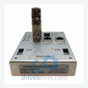
MKS CDN500R Series: Comprehensive Module Range and Technical Overview The MKS CDN500R series is a dedicated line of interlock and…
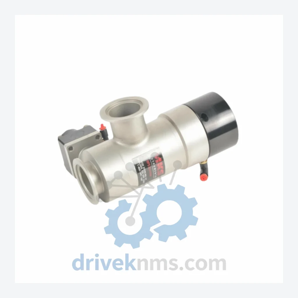
Model: 93-6127 796-801289-001VLV.2 STAGE
Product Overview
Commercial availability is handled through direct RFQ, model verification and export-oriented follow-up rather than public cart checkout.
Datasheet Preview
Use attached product manuals when available. If the manual is not public yet, request the full file directly through RFQ.
Commercial Path
Product pages on DRIVEKNMS are designed to verify model, brand and series first, then move the buyer into one clean quotation path.
Technical Dossier
The MKS 93-6127 / 796-801289 series represents a line of valve positioner input modules deployed extensively in heavy industrial environments including petrochemical refineries, nuclear power auxiliary systems, and large-scale chemical processing plants. These modules serve as the signal conditioning and stage-input interface layer within distributed control system (DCS) architectures, translating field-level valve position feedback into process-compatible digital or analog signals. Their robust design and compliance with industrial EMC standards have made them a long-term fixture in facilities where control loop reliability is non-negotiable. The 796-801289-001VLV.2 STAGE variant specifically addresses two-stage input processing, providing dual-channel signal isolation and conditioning for split-range valve control applications.
The 93-6127 module family was introduced as part of MKS's modular DCS I/O platform, designed for backplane-based rack installation compatible with standard 19-inch industrial enclosures. Early revisions (Rev.A / Rev.B) utilized discrete analog signal paths with passive isolation barriers. Subsequent hardware revisions introduced active isolation with galvanic separation rated to 500V DC, improving noise immunity in high-voltage industrial environments such as motor control centers and switchgear rooms.
The 796-801289 sub-series designation identifies the PCB assembly revision and connector pinout standard, which remained backward-compatible across the -001, -002, and -003 suffix variants. The VLV (Valve) suffix confirms the module's application-specific firmware and hardware tuning for valve positioner feedback loops, distinguishing it from general-purpose analog input variants in the same physical form factor. As of 2024, the 93-6127 series has entered the mature/end-of-active-production phase. MKS no longer manufactures new units; however, the installed base across global process industries remains substantial, sustaining strong demand for tested surplus and refurbished stock.
Controllers & CPU Modules
Analog Input (AI) Modules
Digital Input (DI) Modules
Digital Output (DO) Modules
Communication Adapters
Power Supply Modules
With the 93-6127 series in end-of-active-production status, procurement teams at refineries, power utilities, and chemical plants face increasing lead times and diminishing OEM support. DriveKNMS maintains a dedicated inventory of tested surplus MKS 93-6127 and 796-801289 modules sourced from decommissioned plant equipment, authorized distributor overstock, and controlled factory surplus channels.
The 93-6127 and 796-801289 module families present specific quality control challenges due to their backplane bus architecture and multi-layer PCB construction. DriveKNMS applies the following test protocol to all units in this series:
Related Paths
MKS CDN500R Series: Comprehensive Module Range and Technical Overview The MKS CDN500R series is a dedicated line of interlock and…

MKS CDN500-19 0190-07970 Interlock Module – Obsolete MKS Series Spare Part When an interlock module fails in a legacy control…
ALSTOM MVAJ105RA0802A Protection Relay: Supply Continuity Strategy for a Discontinued Critical Component The ALSTOM MVAJ105RA0802A is a numerical protection relay…