OMRON CPM2C-8EDM CPU Unit – Obsolete CPM2C Series Spare Part
OMRON CPM2C-8EDM CPU Unit – Obsolete CPM2C Series Spare Part When an OMRON CPM2C-8EDM CPU unit fails on the production…
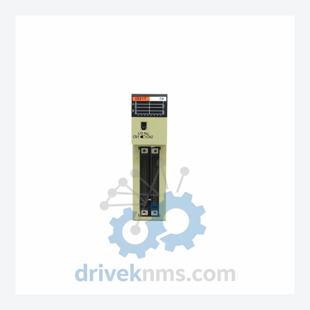
Model: C200H-ID217
Product Overview
Commercial availability is handled through direct RFQ, model verification and export-oriented follow-up rather than public cart checkout.
Datasheet Preview
Use attached product manuals when available. If the manual is not public yet, request the full file directly through RFQ.
Commercial Path
Product pages on DRIVEKNMS are designed to verify model, brand and series first, then move the buyer into one clean quotation path.
Technical Dossier
The OMRON C200H is a modular programmable logic controller platform that achieved widespread deployment across global heavy industry from the mid-1980s through the 2000s. Installations span petrochemical refineries, chemical processing plants, nuclear auxiliary systems, pulp and paper mills, and automotive assembly lines. The C200H backplane architecture supports mixed I/O and specialty module configurations, making it a long-lived platform for both greenfield installations and legacy maintenance programs. Its rack-based design — supporting up to 10 I/O slots per CPU rack — enabled scalable configurations from small standalone cells to distributed multi-rack systems. Despite its end-of-production status, the C200H remains active in thousands of facilities where full DCS migration is deferred due to cost, process continuity requirements, or regulatory constraints.
The C200H platform was introduced by OMRON in the mid-1980s as a successor to the C200 series, incorporating an enhanced backplane bus, expanded I/O addressing, and support for intelligent modules. The original CPU units — C200H-CPU01-E and C200H-CPU03-E — used a proprietary instruction set with ladder diagram programming via SYSMAC Support Software. By the early 1990s, OMRON introduced the C200HS as a transitional upgrade, followed by the C200HX/HG/HE family in the mid-1990s, which extended memory capacity, added floating-point arithmetic, and introduced FINS (Factory Interface Network Service) communication natively. The C200H I/O modules maintained backward compatibility across these generations, allowing existing field wiring to be retained during CPU upgrades. The platform entered its end-of-life phase progressively from 2005 onward, with OMRON officially discontinuing manufacturing of most C200H modules by 2010–2015. Replacement pathways include migration to the CJ2 and NX series, though direct module-for-module substitution requires I/O mapping and program conversion. For facilities maintaining original C200H hardware, sourcing verified used and refurbished modules from specialist distributors is the primary lifecycle extension strategy.
The following SKUs represent verified, commonly deployed modules within the C200H platform. Modules are classified by functional category.
Digital Input Modules (DI)
Digital Output Modules (DO)
Analog Modules (AI/AO)
CPU Modules
Communication & Specialty Modules
Power Supply Modules
C200H modules present specific test challenges due to their backplane bus architecture and mixed-voltage I/O designs. DriveKNMS applies the following verification procedures to all C200H units prior to dispatch:
© 2026 DriveKNMS. All trademarks belong to their respective owners. Specifications are for reference only and subject to change without notice. Verify all parameters against official documentation before installation.
Related Paths
OMRON CPM2C-8EDM CPU Unit – Obsolete CPM2C Series Spare Part When an OMRON CPM2C-8EDM CPU unit fails on the production…
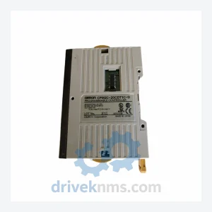
OMRON CPM2C-20CDT1C-D: Sourcing Strategy & Asset Return Value in a Constrained Global Supply Chain The OMRON CPM2C-20CDT1C-D is a compact,…
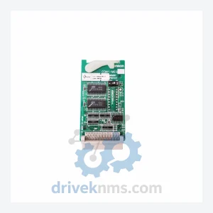
OMRON CQM1-ME04K / CQM1-ME08K PLC Memory Module: Procurement Strategy & Asset ROI in a Constrained Supply Environment The OMRON CQM1-ME04K…