Technical Dossier
Product Details And Specifications
PHOENIX CONTACT MCR-C Series: Comprehensive Module Range and Technical Overview
The PHOENIX CONTACT MCR-C series represents one of the most widely deployed families of DIN-rail-mounted signal conditioners in global heavy industry. Installed across petrochemical complexes, nuclear power stations, offshore platforms, and refinery control rooms, MCR-C modules serve as the signal interface layer between field instrumentation and DCS/PLC systems. Their compact 6.2 mm and 12.5 mm housing widths allow high-density marshalling cabinet layouts, a critical requirement in brownfield retrofit projects where panel space is constrained. The series supports NAMUR NE43-compliant signal ranges and is certified to IEC 60947-5-6, making it a default specification in safety-instrumented system (SIS) auxiliary loops worldwide.
The Evolution of MCR-C Architecture
The MCR-C lineage originates from PHOENIX CONTACT's late-1990s MACX Analog signal conditioner platform, which established the 6.2 mm pitch form factor that became an industry benchmark. The MCR-C designation was introduced to consolidate a fragmented product range into a unified, function-coded naming convention: MCR (Measurement, Control, Regulation) followed by a suffix string encoding input type, output type, and special function (e.g., DCI for DC isolation, PT for Pt100 input, TC for thermocouple).
First-generation MCR-C modules used optocoupler-based isolation with 500 V AC working isolation. Second-generation units introduced transformer-based galvanic isolation rated to 1500 V AC, meeting IEC 61010-1 reinforced insulation requirements for use in Zone 2 hazardous areas when paired with appropriate barriers. Current production modules incorporate SMD assembly and conformal coating as standard, extending MTBF beyond 500,000 hours per Siemens SN 29500 calculation.
Compatibility note: MCR-C modules use the same 35 mm DIN rail clip and 2.5 mm² screw terminal pitch as the predecessor MACX series, allowing physical substitution in existing marshalling racks. However, the MCR-C-SL sub-family introduced a snap-in bus connector system incompatible with earlier MACX power bus rails — a common source of integration errors during panel upgrades.
MCR-C Full Catalog & Functionalities (SKU List)
Universal Analog Input / Output Converters
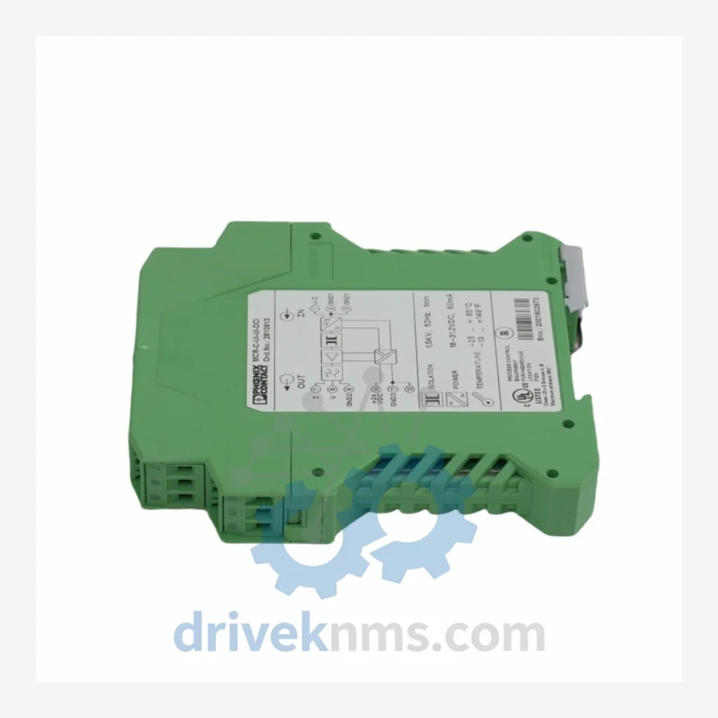
- MCR-C-UI-UI-DCI: Universal input (0–10 V / 0–20 mA / 4–20 mA) to universal output isolation amplifier with DC isolation; 3-way galvanic separation.
- MCR-C-UI-UI: Universal input to universal output signal conditioner; non-isolated variant for cost-sensitive applications.
- MCR-C-UI-2UI-DCI: Single universal input to dual universal output isolation amplifier; used for signal splitting to DCS and historian simultaneously.
- MCR-C-UI-UI-PT-DCI: Universal input to universal output with integrated Pt100 sensor supply; loop-powered transmitter interface.
Current Loop / 4–20 mA Modules
- MCR-C-I-I-DCI: 4–20 mA input to 4–20 mA output galvanic isolation amplifier; standard marshalling module for DCS analog input cards.
- MCR-C-I-I: 4–20 mA to 4–20 mA signal repeater without isolation; used for signal extension over long cable runs.
- MCR-C-I-2I-DCI: Single 4–20 mA input to dual 4–20 mA output splitter with isolation; common in redundant DCS architectures.
- MCR-C-NAMUR-DCI: NAMUR proximity switch input to relay/transistor output signal conditioner; IEC 60947-5-6 compliant.
Voltage Signal Modules
- MCR-C-U-I-DCI: Voltage input (0–10 V) to current output (4–20 mA) converter with galvanic isolation; used for PLC AO to field device interfacing.
- MCR-C-I-U-DCI: Current input (4–20 mA) to voltage output (0–10 V) converter with isolation; interfaces legacy voltage-input recorders.
Temperature Input Modules
- MCR-C-PT100-UI-DCI: Pt100/Pt1000 RTD input to universal analog output transmitter with 3-way isolation; supports 2-wire, 3-wire, and 4-wire RTD connections.
- MCR-C-TC-UI-DCI: Thermocouple input (types J, K, T, E, N, R, S, B) to 4–20 mA / 0–10 V output with cold junction compensation and galvanic isolation.
- MCR-C-RTD-UI-DCI: Multi-range RTD input (Pt100, Ni100, Ni120) to universal output; configurable via DIP switch without software tools.
Frequency / Pulse Modules
- MCR-C-F-UI-DCI: Frequency/pulse input (0.1 Hz–10 kHz) to analog output converter with isolation; used for turbine flow meter and tachometer signal conditioning.
Power Supply / Auxiliary Modules
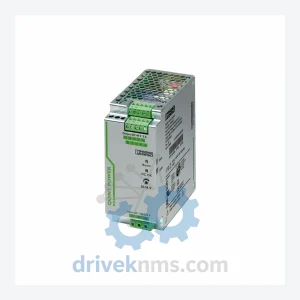
- MCR-C-SL-1: Single-channel power supply module for MCR-C-SL snap-in bus system; 24 V DC input, provides loop power to adjacent signal conditioners.
- MCR-C-SL-2: Dual-channel power supply module for MCR-C-SL bus; supports up to 16 modules per bus segment.
Sourcing Hard-to-Find & Obsolete MCR-C Parts
Several MCR-C variants — particularly early-generation DCI modules with the legacy 5-pin terminal block layout — have reached end-of-life (EOL) status in PHOENIX CONTACT's standard catalog. Affected part numbers include early MCR-C-UI-UI-DCI revisions with hardware revision codes below Rev. 03, and all MCR-C-SL-1 units manufactured before 2015 (identifiable by the gray rather than light-gray housing color per RAL 7035).
DriveKNMS maintains a dedicated inventory of tested surplus and refurbished MCR-C modules to support lifecycle extension programs for DCS installations that cannot be migrated to current-generation MACX MCR or MINI MCR-2 platforms. Our sourcing network covers original factory-sealed stock, tested pulls from decommissioned panels, and recertified units with full functional test documentation.
For plants operating under IEC 61511 functional safety management, we provide traceability documentation including original manufacturer date codes, revision history, and test records — meeting the evidentiary requirements for safety lifecycle audits.
Quality Control for the MCR-C Range
MCR-C modules present specific test challenges due to their transformer-based isolation stages and precision analog signal paths. DriveKNMS applies the following test protocol to all MCR-C units prior to dispatch:
- Isolation resistance test: 500 V DC applied between input, output, and power supply terminals; minimum 100 MΩ required per IEC 61010-1.
- Dielectric withstand test: 1500 V AC for 1 minute across isolation barrier; no breakdown or excessive leakage current permitted.
- Signal accuracy verification: Input swept across full range (0–20 mA or 0–10 V); output measured at 5 calibration points; linearity error must be within ±0.1% of span.
- Temperature coefficient check: For TC and RTD input modules, cold junction compensation accuracy verified at 25°C ambient against NIST-traceable reference.
- Bus communication test (SL variants): Snap-in bus connector continuity and power distribution verified under rated load current.
- Burn-in: 24-hour powered soak at 40°C ambient prior to final calibration check.
All test data is logged per unit serial number and available to customers upon request.
© 2026 DriveKNMS. All trademarks belong to their respective owners. Specifications are for reference only and subject to change without notice. Verify all parameters against official documentation before installation.