
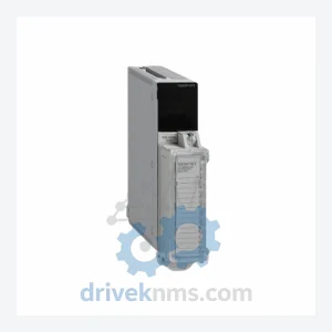
Schneider Electric TSXDEY16A4 Discrete Input Module – Obsolete TSX Premium Spare Part
Schneider Electric TSXDEY16A4 is listed for TSX Premium RFQ review. Confirm quantity, condition and destination before quotation.
RFQ-ready industrial model
Model: PN072545P1
Product Overview
Commercial availability is handled through direct RFQ, model verification and export-oriented follow-up rather than public cart checkout.
Datasheet Preview
Use attached product manuals when available. If the manual is not public yet, request the full file directly through RFQ.
Commercial Path
Product pages on DRIVEKNMS are designed to verify model, brand and series first, then move the buyer into one clean quotation path.
Technical Dossier
Schneider Electric's printed circuit board assemblies for industrial automation evolved through three distinct generations. The first generation (1980s–early 1990s) used through-hole component technology on single or double-layer boards, primarily serving the Modicon 984 and 484 controller families. These boards relied on parallel backplane buses with limited noise immunity and required manual calibration during commissioning.
The third generation (2010s–present) introduced conformal coating as standard, RoHS-compliant component sourcing, and integration with EcoStruxure architecture. Legacy boards from the second generation, including the PN072545P1, are no longer in active production but remain in service at thousands of installed sites. Schneider Electric's official end-of-life (EOL) policy for these assemblies places the responsibility for long-term spares procurement on the end user or authorized third-party suppliers.
The following SKUs represent the broader Schneider Electric PCB and module ecosystem compatible with or related to the PN072545P1 assembly. All models listed are verified part numbers within the Schneider Electric Modicon/Quantum/Premium spare parts catalog:
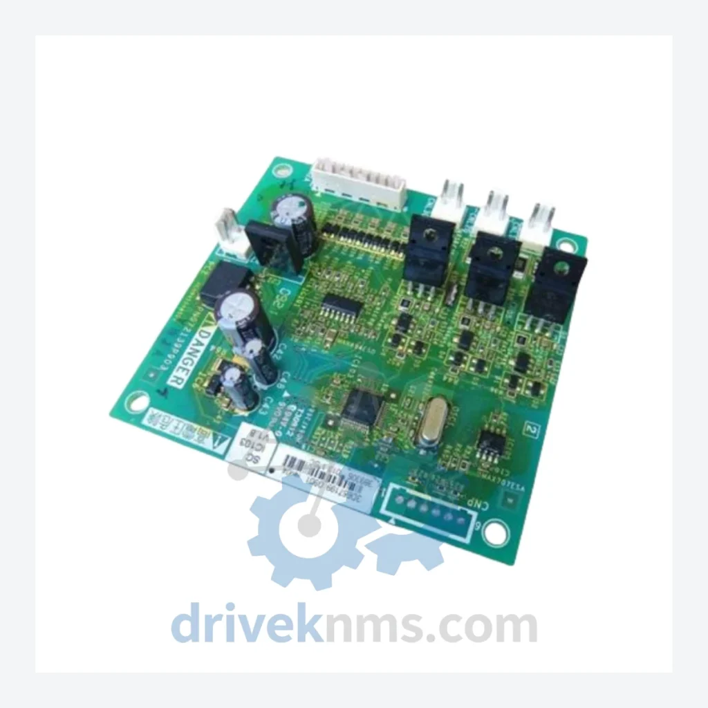
PN072545P1: Main control PCB assembly for Quantum/Premium rack controller chassis
140CPU65150: Quantum Unity CPU module, 1MB user memory, Ethernet + Modbus Plus
140CPU67160: Quantum Unity CPU, dual Ethernet, hot standby capable
140CPS11420: Quantum 115/230 VAC power supply module, 8A output
140CPS21400: Quantum 24 VDC power supply module, 8A
140DAI54000: Quantum 32-channel 24 VDC discrete input module
140DAO84000: Quantum 32-channel 24 VDC discrete output module
140ACI04000: Quantum 8-channel analog current input, 4–20 mA
140ACO02000: Quantum 2-channel analog current output, 4–20 mA
140AVI03000: Quantum 8-channel analog voltage input, ±10 V
140NOE77101: Quantum Ethernet TCP/IP network option module
140NOM21200: Quantum Modbus Plus network option module
140XBP01600: Quantum 16-slot backplane/rack assembly
140XBP00600: Quantum 6-slot backplane/rack assembly
TSXP574634M: Premium Unity CPU, 4MB memory, Ethernet + Modbus
TSXDSY08R5: Premium 8-channel relay output module, 5A per channel
TSXASY410: Premium 4-channel analog I/O mixed module
TSXPSY2600M: Premium 26W power supply module, 24 VDC
BMXP342020: Modicon M340 CPU, Ethernet + serial, 512 I/O
BMXDDI1602: Modicon M340 16-channel 24 VDC discrete input module
Each PN072545P1 unit processed by DriveKNMS undergoes a structured multi-stage inspection protocol designed for complex backplane-interfacing PCB assemblies:
Visual Inspection: 10× magnification examination of all solder joints, component seating, connector pin integrity, and conformal coating condition. Boards with evidence of thermal stress, electrolytic capacitor leakage, or corrosion are quarantined.
In-Circuit Test (ICT): Automated bed-of-nails testing verifies passive component values, continuity of all signal traces, and absence of short circuits across the backplane connector array.
Functional Burn-In: The board is installed in a live Quantum or Premium chassis and subjected to a minimum 48-hour powered burn-in cycle at rated operating temperature (0–60°C), with continuous monitoring of all I/O signal paths and communication bus activity.
Communication Bus Validation: Modbus Plus and Ethernet TCP/IP stack integrity is verified using protocol analyzers. Backplane arbitration timing is measured against Schneider Electric's published specifications.
Final Calibration & Certification: All analog signal paths are calibrated to ±0.1% accuracy. A serialized test certificate is issued with each unit, documenting all test results and the technician's identification.
Continue The Model Path
Move from this exact model into the matching system hub, brand archive, model-family archive or lifecycle sourcing route before sending a final RFQ list.
Related Paths
Schneider Electric TSXDEY16A4 is listed for TSX Premium RFQ review. Confirm quantity, condition and destination before quotation.
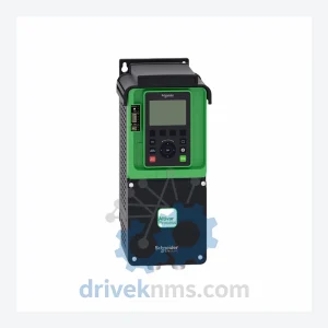
Schneider Electric ATV930D37N4 is listed for Altivar Process Series RFQ review. Confirm quantity, condition and destination before quotation.
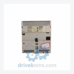
Schneider Electric 170ADO34000 is listed for Modicon Momentum RFQ review. Confirm quantity, condition and destination before quotation.