Vibro-Meter VM600 CPU-M 200-595-075-122 CPU Card – Obsolete VM600 Spare Part
Vibro-Meter VM600 CPU-M 200-595-075-122 CPU Card – Obsolete VM600 Spare Part When the CPU-M card in a VM600 rack fails,…
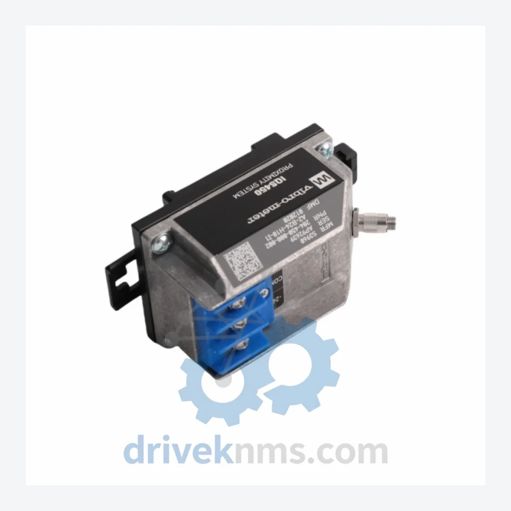
Model: IQS450 S3960 204-450-000-002
Product Overview
Commercial availability is handled through direct RFQ, model verification and export-oriented follow-up rather than public cart checkout.
Datasheet Preview
Use attached product manuals when available. If the manual is not public yet, request the full file directly through RFQ.
Commercial Path
Product pages on DRIVEKNMS are designed to verify model, brand and series first, then move the buyer into one clean quotation path.
Technical Dossier
The Vibro-Meter IQS450 is a modular proximity measurement system developed by Meggitt SA (formerly Vibro-Meter SA), headquartered in Fribourg, Switzerland. The IQS450 platform is deployed globally in heavy industrial environments including petrochemical refineries, nuclear power stations, offshore platforms, and rotating machinery protection systems. It serves as a primary signal conditioning and measurement chain for eddy-current proximity probes, providing continuous shaft displacement, vibration, and position monitoring in accordance with API 670 machinery protection standards. The system's modular backplane architecture allows integration into distributed control systems (DCS) and safety instrumented systems (SIS), making it a standard reference in turbomachinery monitoring installations worldwide.
The IQS450 series succeeded the earlier Vibro-Meter VM600 and IQS4x0 families, consolidating signal conditioning, power distribution, and communication functions into a unified rack-based architecture. Early IQS450 variants operated with analog 4–20 mA output loops and discrete relay trip outputs, compatible with legacy DCS platforms from Honeywell, ABB, and Emerson. Subsequent hardware revisions introduced digital fieldbus interfaces (PROFIBUS-DP, Modbus RTU) and expanded the channel density per rack slot. The S3960 sub-series, to which part number 204-450-000-002 belongs, represents the proximity signal conditioner variant optimized for eddy-current probe inputs with configurable gap, vibration, and speed measurement modes. Compatibility considerations arise when mixing early-revision backplanes (pre-2005) with later-generation I/O modules; firmware alignment and backplane bus protocol versions must be verified before substitution. As of 2024, the IQS450 series is in the mature/end-of-active-production phase; Meggitt continues to offer spare parts and repair services, but new installations are directed toward the VM600 MPC4 and VC-8 platforms. Long-term maintenance support for IQS450 remains critical for operators with 15–25 year plant lifecycles who cannot justify full system replacement.
Proximity Signal Conditioners
Vibration Signal Conditioners
Power Supply Modules
Communication & Interface Modules
Relay & Trip Output Modules
Backplane & Rack Hardware
IQS450 modules present specific test challenges due to their precision analog signal conditioning circuits, backplane bus communication protocols, and configurable trip relay logic. DriveKNMS applies a structured test protocol for each IQS450 unit processed: (1) Visual and mechanical inspection of connector pins, backplane edge connectors, and PCB surface for corrosion, thermal damage, or component failure. (2) Power-on functional test at rated supply voltage (24 VDC ±10%), verifying output signal levels against factory calibration specifications. (3) Proximity conditioner modules (S3960 series) are tested using a calibrated eddy-current probe simulator to verify gap voltage output linearity, vibration AC output bandwidth, and speed pulse output accuracy. (4) Communication modules are tested for PROFIBUS-DP or Modbus register map integrity using protocol analyzers. (5) Relay output modules are tested for contact resistance, trip threshold accuracy, and latching/non-latching logic behavior. (6) Final burn-in at operating temperature for a minimum of 4 hours prior to shipment. Each unit is issued a test report with measured parameters and pass/fail criteria referenced to Vibro-Meter factory specifications.
© 2026 DriveKNMS. All trademarks belong to their respective owners. Specifications are for reference only and subject to change without notice. Verify all parameters against official documentation before installation.
Related Paths
Vibro-Meter VM600 CPU-M 200-595-075-122 CPU Card – Obsolete VM600 Spare Part When the CPU-M card in a VM600 rack fails,…
VIBRO-METER CMC16 Series: Comprehensive Module Range and Technical Overview The VIBRO-METER CMC16 series is a rack-mounted condition monitoring platform engineered…
VIBRO-METER VM600 CMC16 200-530-023-014 / 200-530-100-014: Securing Supply Continuity for Mission-Critical Condition Monitoring Systems The VIBRO-METER VM600 CMC16 (Part Numbers:…