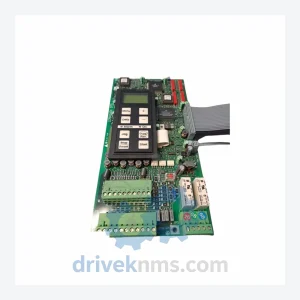
Danfoss 175H3828 DT5 175H7068 Power Board – FC Series
Danfoss 175H3828 DT5 175H7068 Power Board: Strategic Sourcing in a Constrained Supply Chain The Danfoss 175H3828 (also referenced as DT5…
Model: 175Z1213 DT16
Product Overview
Commercial availability is handled through direct RFQ, model verification and export-oriented follow-up rather than public cart checkout.
Datasheet Preview
Use attached product manuals when available. If the manual is not public yet, request the full file directly through RFQ.
Commercial Path
Product pages on DRIVEKNMS are designed to verify model, brand and series first, then move the buyer into one clean quotation path.
Technical Dossier
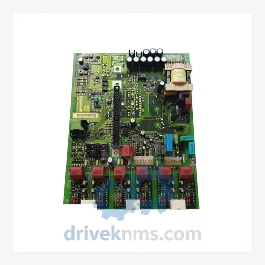
The Danfoss DT16 Series driver boards are core control components deployed across global heavy industry installations, including petrochemical refineries, offshore platforms, pulp and paper mills, water treatment facilities, and nuclear auxiliary systems. The DT16 platform serves as the gate-drive and firing-circuit backbone within Danfoss medium-voltage and industrial drive systems, providing reliable IGBT/thyristor triggering, fault isolation, and feedback signal conditioning. Installed base spans multiple continents, with documented deployments in facilities operated by major EPC contractors and national energy utilities. The series is recognized for its long operational lifespan under continuous-duty conditions and its compatibility with legacy Danfoss VLT and MCD drive enclosures.
The DT16 architecture was introduced as part of Danfoss's second-generation drive control platform, succeeding earlier analog firing boards used in VLT 3000 and VLT 5000 series enclosures. The DT16 introduced hybrid digital-analog gate-drive logic, enabling more precise switching timing and improved EMC performance compared to its predecessors. Early DT16 revisions (Rev. A–C) used through-hole component construction with discrete optocoupler isolation stages. Later revisions (Rev. D onward) transitioned to surface-mount technology (SMT), reducing board footprint and improving thermal management. The series maintained backward mechanical compatibility with the original DT16 mounting frame, allowing field replacement without enclosure modification. As Danfoss migrated its drive platform toward the VLT AutomationDrive FC 302 and FC 102 families, the DT16 entered a maintenance-only lifecycle phase. Cross-compatibility with MCD 500 soft-starter control boards requires adapter harnesses and is not plug-and-play. Engineers specifying replacements must verify firmware revision alignment and gate-drive voltage ratings (typically 15V / -8V for IGBT variants) before substitution.
The following SKUs represent verified, commonly sourced components within the Danfoss DT16 driver board family. Each entry reflects a distinct functional variant or revision level:
175Z1213: DT16 main gate-drive firing board, IGBT trigger output, standard voltage rating
175Z1214: DT16 driver board, high-current IGBT variant, enhanced thermal pad
175Z1215: DT16 Rev. D SMT board, reduced footprint, improved EMC shielding
175Z1216: DT16 auxiliary feedback board, analog signal conditioning, 4–20 mA output
175Z1217: DT16 fault detection sub-board, overcurrent and short-circuit latch
175Z1218: DT16 isolated power supply board, ±15V DC output for gate-drive rails
175Z1219: DT16 communication interface board, RS-485 / Modbus RTU
175Z1220: DT16 thyristor firing board, SCR-compatible, phase-angle control
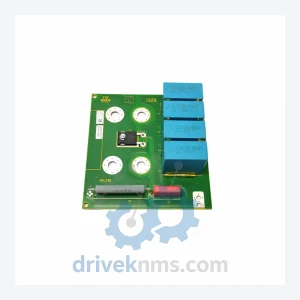
175Z1221: DT16 snubber and clamp board, transient voltage suppression
175Z1222: DT16 temperature monitoring board, NTC/PTC sensor interface
175Z1223: DT16 current sensor interface board, Hall-effect transducer input
175Z1224: DT16 DC bus voltage sensing board, high-voltage divider network
175Z1225: DT16 fan control and thermal management board, PWM output
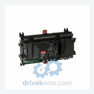
175Z1226: DT16 I/O expansion board, digital input/output, 24V DC logic
175Z1227: DT16 replacement driver board kit, includes mounting hardware and harness
175Z1228: DT16 Rev. E board, updated optocoupler spec, RoHS compliant variant
DriveKNMS maintains a dedicated inventory program for Danfoss DT16 Series components that have reached end-of-production status. As Danfoss has transitioned its drive portfolio to the FC 302 and FC 102 platforms, many DT16 sub-assemblies are no longer available through standard distribution channels. DriveKNMS sources DT16 boards through certified secondary market channels, decommissioned drive enclosures, and direct OEM surplus. All sourced units are subject to incoming inspection before entering available stock. For obsolete revisions (Rev. A–C through-hole boards), DriveKNMS maintains a cross-reference database mapping legacy part numbers to available substitutes. Customers operating facilities with long planned maintenance intervals (10+ years) are advised to establish a consignment stock agreement to ensure continuity of spare parts availability. Emergency same-day dispatch is available for in-stock DT16 units to major logistics hubs in Europe, North America, and Southeast Asia.
DT16 driver boards undergo a structured multi-stage inspection protocol at DriveKNMS before dispatch. Stage 1: Visual inspection — board surface, solder joints, component seating, and connector integrity are examined under magnification. Stage 2: Electrical bench test — gate-drive output voltage levels (15V / -8V), isolation resistance (minimum 100 MΩ at 500V DC), and power supply rail stability are verified using calibrated test equipment. Stage 3: Functional simulation — boards are installed in a representative drive test rig and subjected to simulated firing sequences across the full duty cycle range. Stage 4: Thermal cycling — units are cycled through operating temperature range (−10°C to +55°C) to identify latent solder joint failures. Stage 5: Final documentation — each board is assigned a test record with measured values, inspector ID, and dispatch date. Boards that fail any stage are quarantined and not returned to stock.
Related Paths
Danfoss 175H3828 DT5 175H7068 Power Board: Strategic Sourcing in a Constrained Supply Chain The Danfoss 175H3828 (also referenced as DT5…
Danfoss 175Z Series: Comprehensive Module Range and Technical Overview The Danfoss 175Z series represents a broad family of relay modules,…
Danfoss AK-PC 530 084B8007 Pack Controller: Global Sourcing Strategy & Asset Return Value The Danfoss AK-PC 530 (084B8007) is a…