
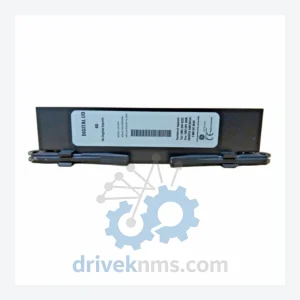
GE UR6DH Digital I/O Module – Critical Spare UR Series Part
GE Grid Solutions UR6DH is listed for Critical Spare UR Series Part RFQ review. Confirm quantity, condition and destination before quotation.
RFQ-ready industrial model
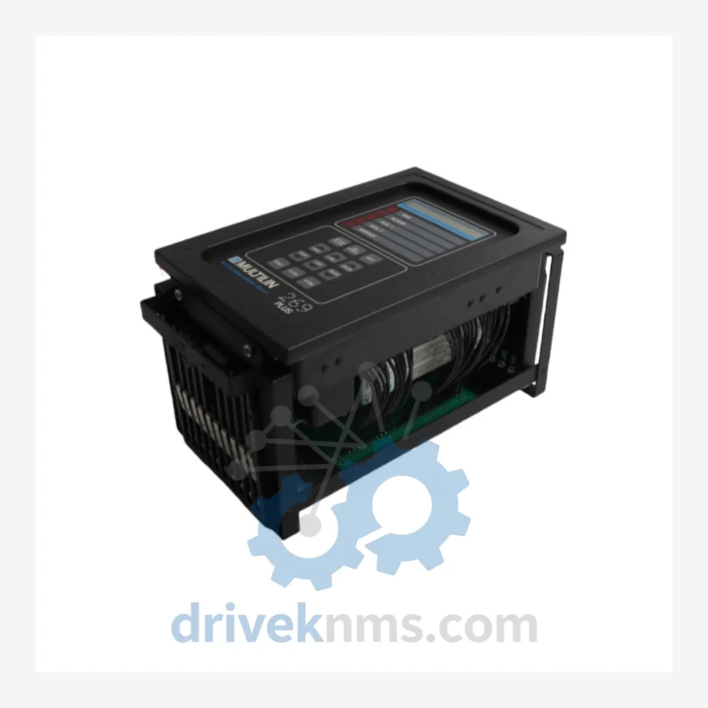
Model: 269PLUS-D/O-100P-125VDC
Product Overview
Commercial availability is handled through direct RFQ, model verification and export-oriented follow-up rather than public cart checkout.
Datasheet Preview
Use attached product manuals when available. If the manual is not public yet, request the full file directly through RFQ.
Commercial Path
Product pages on DRIVEKNMS are designed to verify model, brand and series first, then move the buyer into one clean quotation path.
Technical Dossier
The GE 269 PLUS Motor Management Relay is a microprocessor-based protection and control device engineered for medium-voltage induction and synchronous motors operating in continuous-duty industrial environments. Deployed across petrochemical refineries, nuclear auxiliary systems, offshore platforms, pulp and paper mills, and large-scale water treatment facilities, the 269 PLUS series represents one of the most widely installed motor protection platforms in global heavy industry. Its architecture integrates thermal model protection, current-based fault detection, and serial communications into a single 19-inch rack-mountable or panel-mount chassis, reducing the component count required for comprehensive motor protection schemes. The series remains active in installed base across facilities with 15–30 year asset lifecycles, making spare part availability a critical operational concern for maintenance engineers worldwide.
The GE Multilin 269 series originated as a successor to electromechanical motor protection relays in the late 1980s, introducing microprocessor-based thermal modeling as a replacement for bimetallic overload elements. The original 269 platform established the core protection functions: thermal overload, phase unbalance, undercurrent, ground fault, and jam/stall detection. The 269 PLUS generation extended this foundation with enhanced communications capability (RS-485 Modbus RTU), expanded I/O configurations, and improved metering resolution for current, power factor, and energy consumption.
Key architectural variants within the 269 PLUS generation address different power supply requirements (120 VAC, 125 VDC, 250 VDC), output relay configurations (standard vs. expanded discrete output counts), and communication options. The D/O suffix designates expanded discrete output relay boards, while the 100P suffix indicates a 100:1 CT ratio input configuration. The 125VDC designation specifies the control power supply voltage, a critical parameter for DC-bus substation environments common in petrochemical and utility applications.
Compatibility considerations: 269 PLUS modules are not directly interchangeable with the later 269 PLUS+ (Plus-Plus) or the SR469 Motor Management Relay, which introduced IEC 61850 GOOSE messaging and expanded protection element sets. Facilities migrating from 269 PLUS to SR469 require new CT wiring, revised setting files, and updated HMI configurations. For sites committed to maintaining 269 PLUS infrastructure, sourcing verified replacement units is the operationally lower-risk path.
The following SKUs represent verified models within the GE Multilin 269 PLUS product family, organized by functional category:
Motor Protection & Control – Core Relay Units
Communication & Interface Modules
Accessories & Ancillary Components
Each 269 PLUS unit processed by DriveKNMS undergoes a structured functional verification protocol specific to the relay's protection element architecture:
Continue The Model Path
Move from this exact model into the matching system hub, brand archive, model-family archive or lifecycle sourcing route before sending a final RFQ list.
Related Paths
GE Grid Solutions UR6DH is listed for Critical Spare UR Series Part RFQ review. Confirm quantity, condition and destination before quotation.
GE Grid Solutions UR6AV is listed for UR Series RFQ review. Confirm quantity, condition and destination before quotation.
GE Grid Solutions UR8LV is listed for Controller Cards RFQ review. Confirm quantity, condition and destination before quotation.