
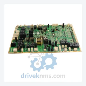
GE IS200WETBH1BAA Elevator Control Board – Obsolete Speedtronic Spare Part
General Electric IS200WETBH1BAA is listed for Speedtronic RFQ review. Confirm quantity, condition and destination before quotation.
RFQ-ready industrial model
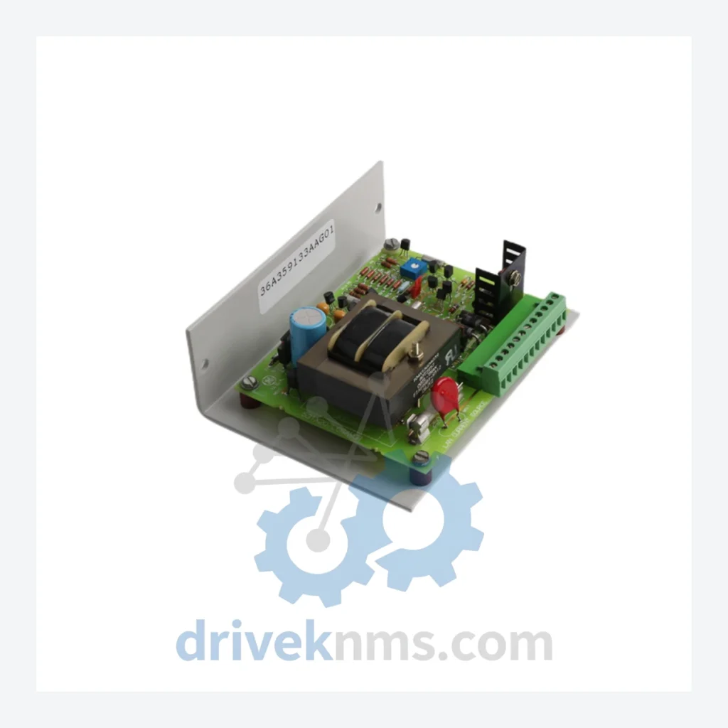
Model: 531X207LCSAMG1
Product Overview
Commercial availability is handled through direct RFQ, model verification and export-oriented follow-up rather than public cart checkout.
Datasheet Preview
Use attached product manuals when available. If the manual is not public yet, request the full file directly through RFQ.
Commercial Path
Product pages on DRIVEKNMS are designed to verify model, brand and series first, then move the buyer into one clean quotation path.
Technical Dossier
The GE 531X series represents a family of printed circuit board assemblies engineered for GE's industrial AC and DC drive platforms, including the GE Drive Systems 6kV ACS, EX2100, and associated variable-speed drive (VSD) control architectures. These boards are deployed across heavy industrial sectors including petrochemical refineries, nuclear power auxiliary systems, offshore platforms, steel mills, and large-scale water treatment facilities. The 531X series functions as the embedded intelligence layer within drive cabinets, handling analog signal conditioning, LAN communications, current feedback, firing pulse generation, gate driver interfacing, and power supply regulation. Due to the long operational lifecycles of industrial drive systems—often 15 to 25 years—531X boards remain in active service globally and represent a critical spare parts category for maintenance engineers and reliability teams.
The 531X board family was introduced as part of GE's modular drive control philosophy in the late 1980s and early 1990s, designed to replace monolithic analog control circuits with discrete, field-replaceable digital and mixed-signal PCB assemblies. Early revisions (suffix codes -A, -B) used through-hole component technology with EPROM-based firmware. Mid-generation boards (suffix -C, -D) transitioned to surface-mount technology (SMT), improving noise immunity and reducing board footprint. Later revisions introduced onboard EEPROM for parameter retention and enhanced LAN interface compatibility with GE's proprietary serial communication protocols.
Compatibility across revisions is not guaranteed. Suffix codes (e.g., LCSAMG1, LCSAM, PCSA) encode hardware revision, firmware baseline, and functional variant. Substituting a board with a mismatched suffix in a live drive system can result in parameter loss, communication faults, or drive trip events. Always cross-reference the drive's Bill of Materials (BOM) or contact DriveKNMS for verified interchange guidance.
The following SKUs represent verified, commonly sourced models within the GE 531X drive control board family. Each entry reflects a distinct functional role within the drive control architecture:
531X207LCSAMG1: LAN current card assembly; analog current feedback and LAN serial interface for AC drive systems.
531X301APCSAKG1: Analog power supply card; regulated DC rail generation for control board logic circuits.
531X111PCSAAG1: Power supply card assembly; multi-rail output for gate driver and signal conditioning boards.
531X121PCSAAG1: Enhanced power supply card; higher current capacity variant for larger drive frames.
531X158PCSAKG1: Firing circuit card; SCR/IGBT gate pulse generation for rectifier and inverter sections.
531X175PCSAKG1: Regulator card; closed-loop speed and current regulation for DC drive applications.
531X180PCSAKG1: Interface card; analog and digital I/O signal conditioning between control and power sections.
531X183PCSAKG1: Diagnostic card; fault logging, trip history, and drive status monitoring.
531X195PCSAKG1: Communication interface card; serial data link between drive controller and plant DCS/SCADA.
531X196PCSAKG1: Expanded I/O card; additional discrete input/output channels for process interlocks.
531X200PCSAKG1: Gate driver card; isolated IGBT gate drive signals with desaturation protection.
531X201PCSAKG1: Resolver interface card; speed feedback signal conditioning from resolver transducers.
531X202PCSAKG1: Encoder interface card; incremental encoder pulse counting and speed calculation.
531X203PCSAKG1: Analog input card; multi-channel 4–20 mA and ±10 V process signal acquisition.
531X205PCSAKG1: Analog output card; multi-channel DAC outputs for speed reference and torque demand signals.
531X209PCSAKG1: LAN voltage card; DC bus voltage sensing and LAN data transmission for drive monitoring.
531X211PCSAKG1: Temperature monitoring card; thermocouple and RTD input processing for thermal protection.
531X215PCSAKG1: Synchronization card; phase-lock loop circuitry for grid synchronization in regenerative drives.
GE 531X boards present specific test challenges due to their mixed analog/digital architecture, proprietary LAN protocol implementation, and dependency on external drive hardware for full functional verification. DriveKNMS employs the following test protocol for all 531X boards processed through our facility:
Visual Inspection: 10× magnification inspection of all solder joints, component bodies, PCB traces, and connector pins. Boards with evidence of arc damage, corrosion, or mechanical stress fractures are quarantined for component-level assessment before proceeding.
In-Circuit Test (ICT): Automated bed-of-nails testing verifies passive component values (resistors, capacitors, inductors) against reference BOM tolerances. Failed components are replaced with OEM-equivalent parts sourced from authorized component distributors.
Functional Bench Test: Each board is powered using a calibrated bench power supply replicating the drive's internal DC rail voltages. For LAN cards (including 531X207LCSAMG1), the LAN serial interface is exercised using a protocol analyzer to verify correct data framing, baud rate, and error handling. Current feedback circuits are verified against known reference signals across the full measurement range.
Burn-In: Boards are operated at elevated ambient temperature (50°C) for a minimum of 8 hours to screen for infant mortality failures in electrolytic capacitors and semiconductor junctions.
Final Calibration Check: Analog signal paths are verified for offset, gain, and linearity against factory specification sheets where available.
Continue The Model Path
Move from this exact model into the matching system hub, brand archive, model-family archive or lifecycle sourcing route before sending a final RFQ list.
Related Paths
General Electric IS200WETBH1BAA is listed for Speedtronic RFQ review. Confirm quantity, condition and destination before quotation.
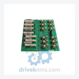
General Electric 531X121PCRALG1 is listed for Mark V Series RFQ review. Confirm quantity, condition and destination before quotation.
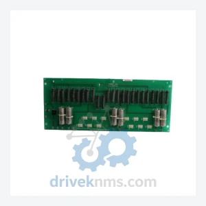
General Electric 531X126SNDAFG1 is listed for Drive Series RFQ review. Confirm quantity, condition and destination before quotation.