
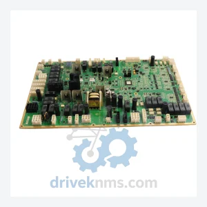
GE IS200WETBH1BAA Elevator Control Board – Obsolete Speedtronic Spare Part
General Electric IS200WETBH1BAA is listed for Controller Cards RFQ review. Confirm quantity, condition and destination before quotation.
RFQ-ready industrial model
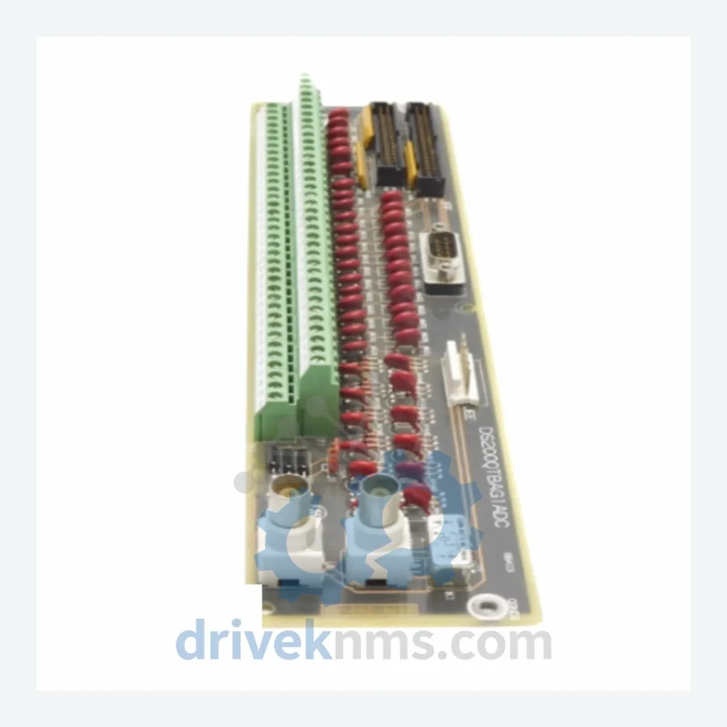
Model: DS200QTBAG1ADC
Product Overview
Commercial availability is handled through direct RFQ, model verification and export-oriented follow-up rather than public cart checkout.
Datasheet Preview
Use attached product manuals when available. If the manual is not public yet, request the full file directly through RFQ.
Commercial Path
Product pages on DRIVEKNMS are designed to verify model, brand and series first, then move the buyer into one clean quotation path.
Technical Dossier
The GE DS200 series represents the core hardware layer of the Speedtronic Mark V turbine control system, developed by General Electric and deployed across gas turbines, steam turbines, and combined-cycle power plants worldwide. Installations span refineries, petrochemical complexes, nuclear auxiliary systems, and LNG terminals across North America, the Middle East, and Asia-Pacific. The DS200 platform has accumulated decades of field hours in environments where control system failure translates directly into unplanned outages measured in millions of dollars per day.
The DS200QTBAG1ADC is a Termination Board within this series, serving as the physical interface layer between field wiring and the Mark V control processor backplane. Termination boards in the DS200 architecture carry signal conditioning, terminal block connectivity, and shielding functions that are critical to I/O signal integrity. A failed or degraded termination board does not merely interrupt one signal — it can render an entire I/O group inoperable, forcing turbine trip or manual shutdown.
Because GE has transitioned its turbine control portfolio toward the Mark VIe platform, the DS200 series is now in end-of-life status. OEM spare parts supply has contracted sharply. Plant engineers managing legacy Mark V installations face a binary choice: source verified DS200 components from specialist distributors, or commit to a full control system migration — a project that routinely exceeds USD 2–5 million per unit and requires extended outage windows. For most operators, extending the service life of existing DS200 hardware through qualified spare parts is the operationally and financially rational path.
The DS200 hardware family was introduced as part of the Speedtronic Mark V control system in the early 1990s. Mark V succeeded the Mark IV and Mark II platforms, introducing a triple-redundant processor architecture (R, S, T controllers) with voting logic to eliminate single-point failures. The DS200 boards were designed to operate within this redundant framework, with each board assigned to a specific functional role within the TCCA, TCQC, SDCC, or TCEA panel assemblies.
Early DS200 revisions used through-hole component construction with discrete logic ICs. Later revisions incorporated surface-mount technology and updated FPGA configurations, improving noise immunity and diagnostic resolution. Firmware versions are board-specific and must match the Mark V software release installed on the host system. Substituting a board with an incompatible firmware revision is a documented failure mode that can cause erratic I/O behavior or processor faults.
GE introduced the Mark VI as a transitional platform in the late 1990s, followed by the Mark VIe in the 2000s, which adopted an Ethernet-based I/O architecture incompatible with DS200 hardware. Plants that have not migrated remain dependent on DS200 inventory. The installed base of Mark V systems globally is estimated in the thousands of units, with a significant proportion still in active commercial operation.
The following DS200 models represent the most commonly sourced components across the Mark V installed base. Each entry reflects a distinct functional role within the control system architecture.
DS200TCQFG1ACC: Turbine Control Quad Core processor board, primary R/S/T voting controller
DS200QTBAG1ADC: Termination board for field I/O wiring interface and signal conditioning
DS200SDCCG1AFG: System Definition and Configuration Card, stores turbine application parameters
DS200TCRAG1ABF: Turbine Control Relay board, manages discrete output relay functions
DS200TCQAG1BHF: Turbine Control Quad board variant, alternate firmware configuration
DS200TCDAH1BHD: Turbine Control Data Acquisition board, analog input processing
DS200TCPDG1AEC: Turbine Control Power Distribution board, internal DC bus management
DS200TCPSG1AEC: Turbine Control Power Supply board, primary 28VDC regulation
DS200TCPAG1AEC: Turbine Control Power Amplifier board, servo output driver
DS200TCEAG1BHF: Turbine Control Excitation board, generator excitation interface
DS200TCEBG1AEC: Turbine Control Excitation Buffer board, signal isolation for excitation circuits
DS200DSPCH1ADA: Digital Signal Processor Communications board, inter-panel data link
DS200IOCAG1AEC: I/O Controller Adapter board, backplane bus arbitration
DS200SLCCG1AEC: Speed and Load Control Card, turbine speed governing logic
DS200EXPSG1AEC: Expansion Power Supply board, auxiliary panel power distribution
DS200TCQCG1AEC: Turbine Control Quad Communications board, serial I/O expansion
DS200GDDAG1AEC: Generator Data Display Adapter, HMI interface for operator panels
All DS200 inventory at DriveKNMS is catalogued by part number, revision suffix, and firmware version where applicable. Customers are advised to specify the full part number including suffix (e.g., DS200QTBAG1ADC) when requesting a quote, as suffix variants may carry different connector configurations or firmware loads that affect drop-in compatibility.
DS200 termination boards and processor cards undergo a structured five-stage inspection protocol at DriveKNMS before any unit is offered for sale:
1. Visual and Mechanical Inspection: Full board examination for cracked PCB traces, damaged connector pins, corroded terminal blocks, and physical impact damage. Termination boards receive particular scrutiny on screw terminal torque and contact plating condition.
2. Electrolytic Capacitor Assessment: All electrolytic capacitors are tested for ESR (Equivalent Series Resistance) and capacitance value. Aged capacitors exhibiting drift beyond 20% of rated value are replaced with equivalent-specification components before the board is cleared.
3. Firmware Version Verification: Where firmware is stored on-board (EPROM or Flash), the version is read and documented. Boards with unknown or mismatched firmware are flagged and not sold as drop-in replacements without customer confirmation of compatibility.
4. Connector and Pin Integrity Check: All edge connectors and backplane interface pins are inspected under magnification. Bent, oxidized, or intermittent-contact pins are corrected or the board is downgraded to parts-only status.
5. Functional Bench Test (where applicable): Processor and I/O boards are powered in a controlled bench environment to verify basic operational status. Boards that fail bench test are not sold as functional units.
Continue The Model Path
Move from this exact model into the matching system hub, brand archive, model-family archive or lifecycle sourcing route before sending a final RFQ list.
Related Paths
General Electric IS200WETBH1BAA is listed for Controller Cards RFQ review. Confirm quantity, condition and destination before quotation.
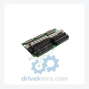
General Electric IS200TRLYH1BED IS200TRLYH1B is listed for Controller Cards RFQ review. Confirm quantity, condition and destination before quotation.
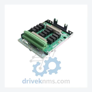
General Electric IS230SNRLH2A IS200SRLYH2AAA is listed for Controller Cards RFQ review. Confirm quantity, condition and destination before quotation.