
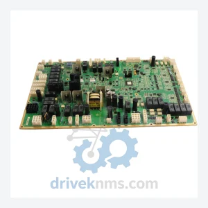
GE IS200WETBH1BAA Elevator Control Board – Obsolete Speedtronic Spare Part
General Electric IS200WETBH1BAA is listed for Speedtronic RFQ review. Confirm quantity, condition and destination before quotation.
RFQ-ready industrial model
Model: DS200TCQAG1A
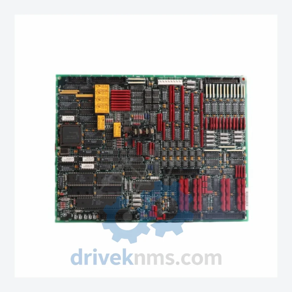
Product Overview
Commercial availability is handled through direct RFQ, model verification and export-oriented follow-up rather than public cart checkout.
Datasheet Preview
Use attached product manuals when available. If the manual is not public yet, request the full file directly through RFQ.
Commercial Path
Product pages on DRIVEKNMS are designed to verify model, brand and series first, then move the buyer into one clean quotation path.
Technical Dossier
The DS200 module family was introduced alongside the Mark V control platform in the early 1990s as GE Power's successor to the Mark IV relay-logic systems. The original Mark V architecture used a three-controller redundancy model (R, S, T controllers) with DS200-series boards handling all analog signal conditioning, digital I/O interfacing, and inter-controller communications via the IONET and ARCNET serial buses.
With the transition to Mark VI in the late 1990s and early 2000s, GE introduced the IS200 and IS215 module families as the primary I/O platform, while DS200 boards remained in service as legacy components in Mark V installations. Many DS200 boards are physically and electrically incompatible with Mark VI racks — a critical compatibility constraint for maintenance engineers planning cross-generation upgrades. The DS200 series entered its end-of-active-production phase circa 2010–2015, with GE Vernova (formerly GE Gas Power) transitioning support to the Mark VIe platform. As of 2026, DS200 modules are classified as mature/end-of-life (EOL) components, available exclusively through authorized aftermarket distributors and certified repair facilities.
The following SKUs represent verified, commonly deployed modules within the GE DS200 series. Each entry reflects a distinct functional role within the Mark V/VI control architecture.
Analog & Signal Conditioning Boards
Digital I/O Boards
CPU & Controller Boards
Power Supply & Backplane Boards
For operators running Mark V systems beyond their original design life, DriveKNMS provides the following lifecycle extension services: board-level repair and component replacement for common failure modes (capacitor degradation, EPROM corruption, relay contact wear); functional testing against OEM-equivalent test procedures; traceability documentation for regulated industries including nuclear auxiliary and offshore oil & gas; and emergency urgent RFQ handling for critical plant outage scenarios.
DS200 modules present specific test challenges due to their multi-bus backplane architecture and mixed analog/digital signal paths. DriveKNMS applies the following test protocol to all DS200 boards prior to dispatch:
Continue The Model Path
Move from this exact model into the matching system hub, brand archive, model-family archive or lifecycle sourcing route before sending a final RFQ list.
Related Paths
General Electric IS200WETBH1BAA is listed for Speedtronic RFQ review. Confirm quantity, condition and destination before quotation.
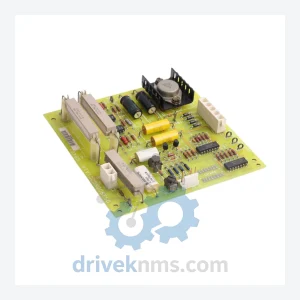
General Electric DS3800NGDC1A1A is listed for Mark IV Series RFQ review. Confirm quantity, condition and destination before quotation.
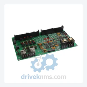
General Electric DS200DDTBG2ABB is listed for Mark VI RFQ review. Confirm quantity, condition and destination before quotation.