
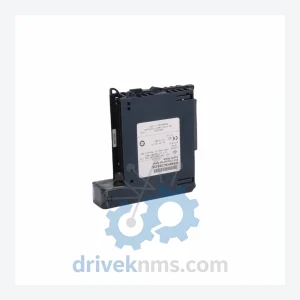
GE Automation & Controls IC695HSC304
GE Automation & Controls IC695HSC304 is listed for PACSystems RX3i RFQ review. Confirm quantity, condition and destination before quotation.
RFQ-ready industrial model
Model: EPSCPE100-BETA
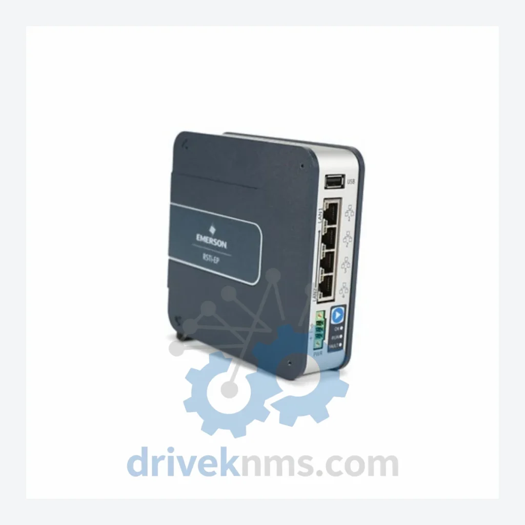
Product Overview
Commercial availability is handled through direct RFQ, model verification and export-oriented follow-up rather than public cart checkout.
Datasheet Preview
Use attached product manuals when available. If the manual is not public yet, request the full file directly through RFQ.
Commercial Path
Product pages on DRIVEKNMS are designed to verify model, brand and series first, then move the buyer into one clean quotation path.
Technical Dossier
The GE EPS (Ethernet Programmable Standalone) Series represents a critical tier in GE Automation & Controls' programmable controller portfolio, deployed extensively across global heavy industry verticals including petrochemical refineries, nuclear power generation facilities, offshore oil & gas platforms, and continuous-process chemical plants. Built on GE's Proficy Machine Edition programming environment, EPS Series controllers deliver deterministic scan-cycle execution, native Ethernet/IP connectivity, and a modular I/O architecture that integrates directly with GE's broader PACSystems and Series 90 ecosystems. The EPSCPE100-BETA standalone controller—the anchor SKU of this page—functions as a self-contained CPU unit capable of executing ladder logic, function block diagram, and structured text programs without a dedicated backplane chassis, making it a preferred choice for distributed machine-level control in space-constrained panel environments.
The EPS Series emerged as GE's response to the growing demand for Ethernet-native standalone controllers that could bridge legacy serial-bus PLCs and modern Industrial Ethernet networks without full system replacement. Early EPS deployments relied on RS-232 and RS-485 serial programming ports, with Ethernet added as a secondary option. Subsequent hardware revisions introduced dual Ethernet ports for device-level ring (DLR) topology support, enabling fault-tolerant network configurations without external managed switches. The EPSCPE100 platform introduced the BETA firmware variant, which extended the instruction set to support advanced motion sequencing primitives and expanded the user program memory ceiling. Compatibility considerations are significant: EPS Series I/O modules use a proprietary local expansion bus that is not pin-compatible with GE Series 90-30 or PACSystems RX3i backplane modules, requiring careful BOM validation during system upgrades. For facilities running mixed GE controller generations, EPS modules can communicate upstream via EGD (Ethernet Global Data) or Modbus TCP, preserving integration with SCADA and DCS historian layers.
The following catalog covers verified EPS Series module SKUs, organized by functional category. Each entry reflects a distinct hardware role within the EPS architecture.
CPU / Standalone Controllers
Digital Input (DI) Modules
Digital Output (DO) Modules
Analog Input (AI) Modules
Analog Output (AO) Modules
Communication & Network Adapters
Power Supply Modules
EPS Series modules present specific test challenges due to their integrated Ethernet stack, local expansion bus arbitration logic, and firmware-dependent instruction execution. DriveKNMS applies the following test protocol to all EPS Series units processed through its facility:
Continue The Model Path
Move from this exact model into the matching system hub, brand archive, model-family archive or lifecycle sourcing route before sending a final RFQ list.
Related Paths
GE Automation & Controls IC695HSC304 is listed for PACSystems RX3i RFQ review. Confirm quantity, condition and destination before quotation.
GE Automation & Controls IC660EBA026 is listed for Genius I/O RFQ review. Confirm quantity, condition and destination before quotation.
GE Automation & Controls IC697MDL940 is listed for Series 90-70 RFQ review. Confirm quantity, condition and destination before quotation.