
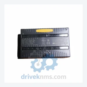
GE IC200MDD845D Discrete I/O Module – Obsolete VersaMax Spare Part
GE Fanuc IC200MDD845D is listed for Versamax RFQ review. Confirm quantity, condition and destination before quotation.
RFQ-ready industrial model
Model: IC200ALG230
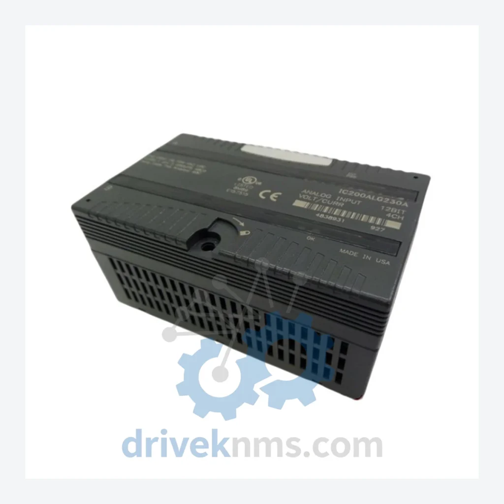
Product Overview
Commercial availability is handled through direct RFQ, model verification and export-oriented follow-up rather than public cart checkout.
Datasheet Preview
Use attached product manuals when available. If the manual is not public yet, request the full file directly through RFQ.
Commercial Path
Product pages on DRIVEKNMS are designed to verify model, brand and series first, then move the buyer into one clean quotation path.
Technical Dossier
The GE Fanuc VersaMax IC200 series is a modular programmable logic controller (PLC) platform deployed across global heavy industry sectors including petrochemical refineries, nuclear power generation facilities, offshore oil & gas platforms, and continuous-process chemical plants. Introduced in the mid-1990s as a successor to the Series 90 Micro platform, the IC200 architecture established a distributed I/O standard that remains embedded in thousands of installed base systems worldwide. Its compact rail-mount form factor, deterministic scan-cycle performance, and broad I/O density made it the default automation backbone for mid-scale process control applications requiring sub-100ms response times. Despite GE's divestiture of its automation division to Emerson (now rebranded under the Movicon/PACSystems umbrella), the IC200 installed base continues to operate in facilities with 20+ year asset lifecycles, creating sustained demand for original spare parts, tested replacements, and lifecycle extension support.
The VersaMax IC200 platform was engineered around a proprietary backplane bus operating at 5VDC logic with a parallel I/O expansion architecture. Early revisions (circa 1996–2001) used the IC200CPU001 and IC200CPU002 processors with RS-232/RS-485 serial communications as the primary network interface. The introduction of the IC200CPU005 and IC200CPUE05 variants added Ethernet TCP/IP capability, enabling integration with SCADA systems and historian platforms without external communication bridges.
The I/O subsystem expanded progressively: initial releases covered discrete 24VDC and 120VAC I/O; subsequent generations added high-density analog modules (12-bit and 15-bit resolution), thermocouple/RTD input modules, and high-speed counter modules for encoder feedback. The IC200 backplane supports up to 8 I/O modules per local rack, with remote expansion via the IC200BEM002 Bus Expansion Module connecting up to 7 remote racks over a proprietary serial link.
Analog Input Modules
Analog Output Modules
Discrete Input Modules
Discrete Output Modules
CPU & Communication Modules
Power Supply Modules
The IC200 backplane bus architecture presents specific test challenges: modules communicate via a parallel data bus with strict timing tolerances, meaning a module that passes basic power-on self-test (POST) may still exhibit intermittent faults under loaded backplane conditions. DriveKNMS applies a three-stage test protocol for all IC200 modules:
Stage 1 — Electrical Baseline: DC rail verification (5V ±2%, 24V ±5%), isolation resistance measurement between field-side and logic-side circuits (>10MΩ at 500VDC), and inrush current profiling on power-up.
Stage 2 — Functional Backplane Test: Each module is installed in a live IC200 test rack running a validated CPU firmware version. Discrete I/O modules are cycled through all points at rated voltage/current. Analog modules are tested across the full input/output range with calibrated signal sources, verifying linearity error <0.1% FSR and channel-to-channel isolation.
Stage 3 — Burn-In & Thermal Soak: Modules are operated continuously for 48 hours at 50°C ambient to screen for early-life component failures. Post-burn-in, all analog calibration parameters are re-verified and documented in a module-specific test certificate shipped with each unit.
Continue The Model Path
Move from this exact model into the matching system hub, brand archive, model-family archive or lifecycle sourcing route before sending a final RFQ list.
Related Paths
GE Fanuc IC200MDD845D is listed for Versamax RFQ review. Confirm quantity, condition and destination before quotation.
GE Fanuc IC200ALG431 is listed for Versamax RFQ review. Confirm quantity, condition and destination before quotation.
GE Fanuc IC670GBI002 is listed for Versamax RFQ review. Confirm quantity, condition and destination before quotation.