
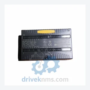
GE IC200MDD845D Discrete I/O Module – Obsolete VersaMax Spare Part
GE Fanuc IC200MDD845D is listed for Versamax RFQ review. Confirm quantity, condition and destination before quotation.
RFQ-ready industrial model
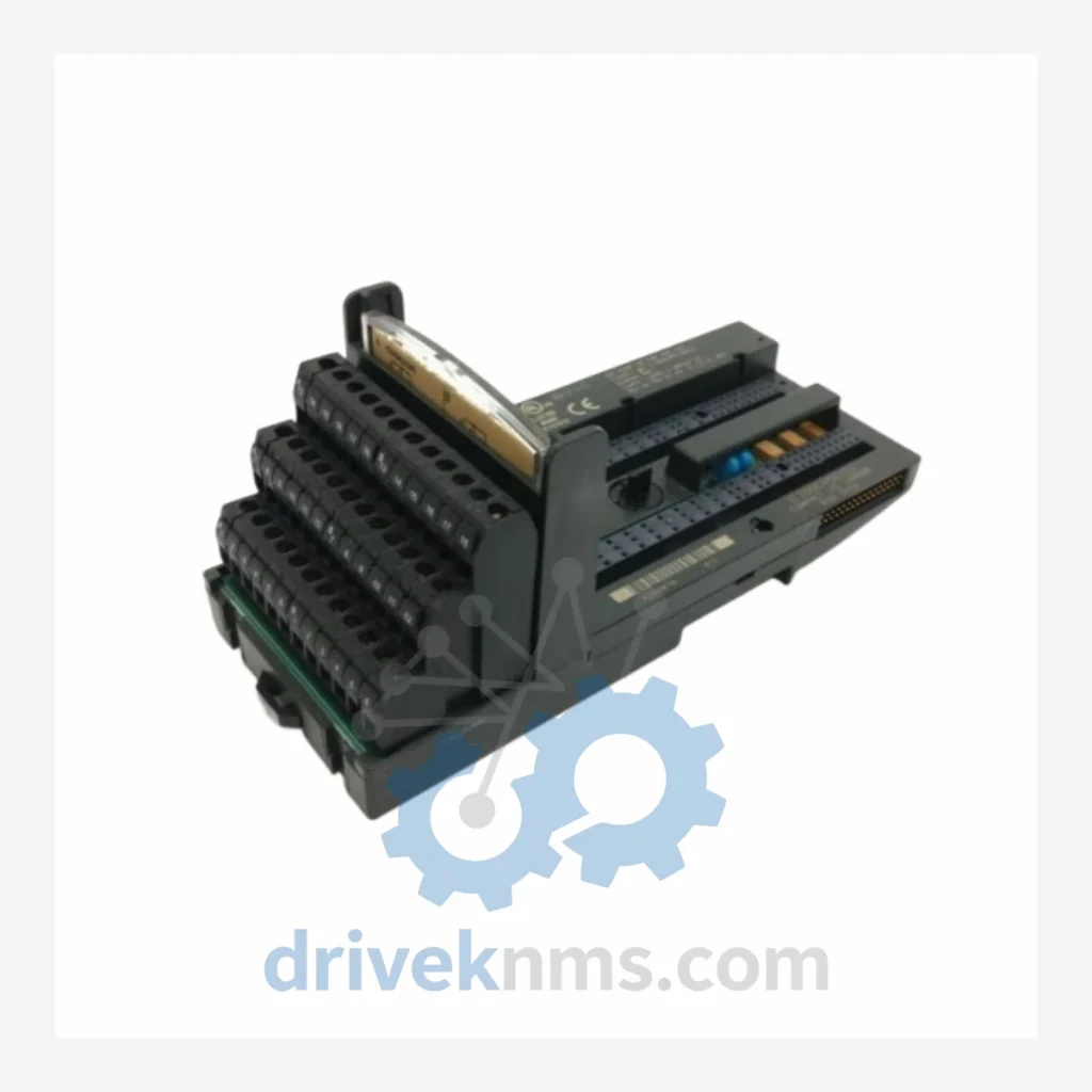
Model: IC200CHS022
Product Overview
Commercial availability is handled through direct RFQ, model verification and export-oriented follow-up rather than public cart checkout.
Datasheet Preview
Use attached product manuals when available. If the manual is not public yet, request the full file directly through RFQ.
Commercial Path
Product pages on DRIVEKNMS are designed to verify model, brand and series first, then move the buyer into one clean quotation path.
Technical Dossier
The IC200CHS022 is a Compact I/O Carrier within this ecosystem, providing the mechanical and electrical backplane interface for VersaMax Compact I/O modules in space-constrained panel installations. It is a passive component — no firmware, no configuration — and serves as the physical mounting and bus interface between the host system and attached I/O modules.
The VersaMax platform was introduced by GE Fanuc Automation in the mid-1990s as a successor to the Series 90 Micro and a complement to the Series 90-30 rack-based systems. The architecture evolved through three distinct phases:
Phase 1 (1996–2002): Initial release of VersaMax Nano and Micro CPUs alongside first-generation I/O carriers. Serial communications (RS-232/RS-485) served as the primary programming interface. Genius Bus was the primary network for distributed I/O. The IC200 prefix was established as the standard module numbering convention.
Phase 2 (2002–2010): Introduction of Ethernet-capable NIUs (Network Interface Units) and expansion of the I/O module catalog. Profibus-DP and DeviceNet adapters were added. The Compact I/O sub-family — including the IC200CHS022 carrier — was introduced to address panel-mount and space-constrained installations. Compatibility with PACSystems RX3i CPUs via VersaMax NIUs was established, enabling hybrid architectures.
Phase 3 (2010–present): GE Intelligent Platforms (rebranded under Emerson following the 2018 acquisition) shifted primary development focus to the PACSystems RX3i and RSTi-EP platforms. VersaMax modules entered a mature/sustaining lifecycle phase. New hardware releases ceased; firmware updates became infrequent. The VersaMax NIU-to-PACSystems migration path remains a supported route for extending the operational life of existing I/O infrastructure without full system replacement. The IC200CHS022 carrier remains in service across this installed base.
The following catalog covers the primary IC200-series module families. All SKUs listed are confirmed VersaMax platform components. Modules are grouped by functional category.
Carriers & Backplanes
CPU & Controller Modules
Digital Input (DI) Modules
Digital Output (DO) Modules
Analog Input (AI) Modules
Analog Output (AO) Modules
Network Interface Units (NIU) & Communications
Power Supply Modules
VersaMax modules present specific test challenges due to their integrated backplane connector interface and bus-dependent communication architecture. DriveKNMS applies the following protocol to IC200-series modules prior to dispatch:
Continue The Model Path
Move from this exact model into the matching system hub, brand archive, model-family archive or lifecycle sourcing route before sending a final RFQ list.
Related Paths
GE Fanuc IC200MDD845D is listed for Versamax RFQ review. Confirm quantity, condition and destination before quotation.
GE Fanuc IC200ALG431 is listed for Versamax RFQ review. Confirm quantity, condition and destination before quotation.
GE Fanuc IC670GBI002 is listed for Versamax RFQ review. Confirm quantity, condition and destination before quotation.