
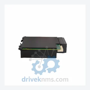
GE UR Series Modules UR6AV Digital I/O Module - UR6AV UR 6AV
GE Grid Solutions UR6AV UR 6AV is listed for Monitoring Systems RFQ review. Confirm quantity, condition and destination before quotation.
RFQ-ready industrial model
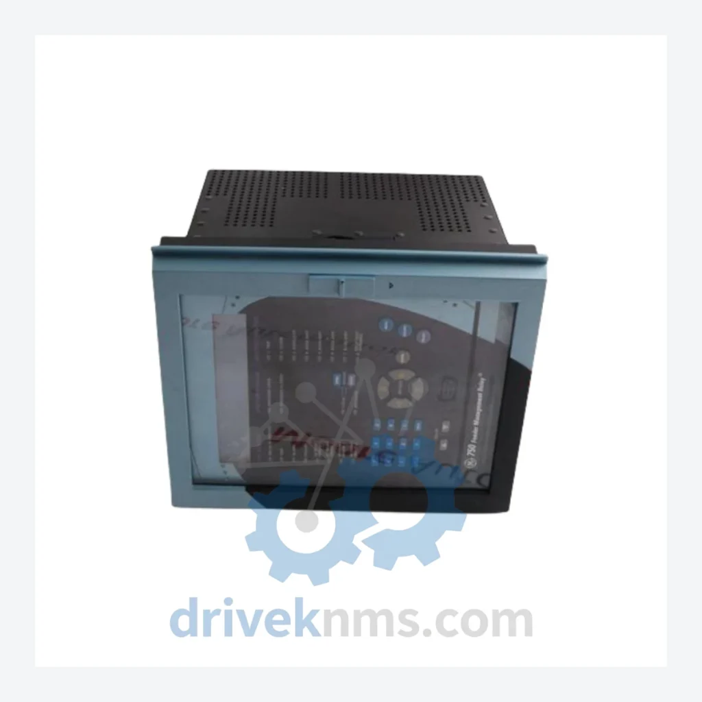
Model: SR750-P5-G5-S5-HI-A20-R
Product Overview
Commercial availability is handled through direct RFQ, model verification and export-oriented follow-up rather than public cart checkout.
Datasheet Preview
Use attached product manuals when available. If the manual is not public yet, request the full file directly through RFQ.
Commercial Path
Product pages on DRIVEKNMS are designed to verify model, brand and series first, then move the buyer into one clean quotation path.
Technical Dossier
The SR750 was introduced in the mid-1990s as part of GE Multilin's SR (System Relay) product family, which also includes the SR469 motor management relay and SR489 generator management relay. The original SR750 architecture was built around a fixed-function hardware platform with RS-485 serial communications (Modbus RTU) and a front-panel keypad/display interface. Firmware was field-upgradeable via serial port, which extended the operational lifespan of early units.
Subsequent hardware revisions introduced expanded I/O configurations, IEC 61850 GOOSE messaging support, DNP3 protocol compatibility, and fiber-optic communication ports. The suffix coding system encodes the hardware configuration directly into the model number: power supply voltage (P5 = 125/250 Vdc, P4 = 48 Vdc), CT input type (G5 = 5A, G1 = 1A), voltage input type (S5 = 5A, S1 = 1A), human interface (HI = enhanced display), analog output count (A20 = 2 analog outputs), and communication options (R = RS-485). This suffix system allows precise cross-referencing of hardware capabilities without consulting the full datasheet.
The following SKUs represent verified, commonly deployed configurations within the GE SR750 feeder management relay series. Each model number encodes specific hardware options per GE Multilin's suffix coding convention.
SR750-P5-G5-S5-HI-A20-R: 125/250Vdc supply, 5A CT, 5A VT, enhanced HMI, 2 analog outputs, RS-485 Modbus — standard feeder protection configuration for industrial MV switchgear.
SR750-P5-G5-S5-HI-A20-E: Identical hardware to above with 10/100Base-T Ethernet port replacing RS-485; supports Modbus TCP and DNP3 over TCP.
SR750-P5-G5-S5-HI-A20-R-E: Dual-port variant with both RS-485 and Ethernet; used in hybrid SCADA architectures requiring simultaneous serial and network connectivity.
SR750-P5-G1-S1-HI-A20-R: 1A CT and 1A VT input configuration; deployed in substations with 1A secondary current transformer installations.
SR750-P4-G5-S5-HI-A20-R: 48 Vdc power supply variant; used in battery-backed DC distribution systems common in utility substations.
SR750-P4-G1-S1-HI-A20-R: 48 Vdc supply with 1A CT/VT inputs; niche configuration for compact utility feeder panels.
SR750-P5-G5-S5-HI-A00-R: No analog outputs; base configuration for installations requiring only digital I/O and protection functions.
SR750-P5-G5-S5-HI-A20-F: Fiber-optic communication port (ST connector); used in high-EMI environments such as arc furnace facilities and traction power substations.
SR750-P5-G5-S5-HI-A20-R-F: RS-485 plus fiber-optic dual-port configuration; supports redundant communication paths in critical infrastructure.
SR750-P5-G5-S5-LO-A20-R: Low-cost HMI variant (LO suffix) with reduced front-panel display; used in applications where local operator interface is not required.
SR750-P5-G5-S5-HI-A20-R-D: DNP3 serial protocol variant over RS-485; common in North American utility SCADA systems using DNP3 as the primary protocol.
SR750-P5-G5-S5-HI-A20-E-D: DNP3 over Ethernet; used in modern utility automation networks with IEC 61968/61970 integration requirements.
SR750-P5-G5-S5-HI-A20-R-61850: IEC 61850 Edition 1 compliant variant with GOOSE messaging; deployed in digital substation automation projects.
SR750-P5-G5-S5-HI-A20-E-61850: IEC 61850 over Ethernet with MMS protocol support; used in IEC 61850-compliant protection schemes requiring peer-to-peer GOOSE blocking.
SR750-P5-G5-S5-HI-A20-R-GPS: IRIG-B time synchronization input variant; used in fault recording and sequence-of-events applications requiring microsecond-level time stamping.
SR750-P5-G1-S1-HI-A20-E: 1A CT/VT with Ethernet; common replacement unit for aging 1A installations being upgraded to network-connected SCADA.
SR750-P5-G5-S5-HI-A20-R-T: Extended temperature range variant; rated for operation in outdoor enclosures or non-climate-controlled switchgear rooms in extreme climates.
For end-of-life SR750 variants — particularly early-revision units with RS-485-only communication and no Ethernet option — DriveKNMS provides tested, refurbished units with documented firmware versions. Each unit is cross-referenced against the GE SR750 instruction manual (GEK-106310) to verify hardware revision compatibility before dispatch. We also supply associated accessories including SR750 test plugs, communication cables (RS-485 to USB adapters), and replacement front-panel display assemblies.
All SR750 units processed by DriveKNMS undergo a structured functional verification protocol prior to dispatch. The test sequence addresses the specific failure modes documented in GE Multilin's SR750 field service bulletins, including power supply capacitor degradation, RS-485 transceiver failure, and EEPROM data corruption in units subjected to repeated power cycling.
Test procedures include: DC power supply input verification across the full rated voltage range (85–300 Vdc for P5 variants; 38–60 Vdc for P4 variants); CT and VT input accuracy verification using a calibrated relay test set (Omicron CMC or equivalent); all digital input and output contact verification under rated load; communication port loopback testing (RS-485 Modbus RTU, Ethernet Modbus TCP, DNP3 as applicable); front-panel HMI display and keypad functional check; and firmware version documentation with compatibility cross-reference to the installed base version.
Continue The Model Path
Move from this exact model into the matching system hub, brand archive, model-family archive or lifecycle sourcing route before sending a final RFQ list.
Related Paths
GE Grid Solutions UR6AV UR 6AV is listed for Monitoring Systems RFQ review. Confirm quantity, condition and destination before quotation.
GE Grid Solutions UR8LV UR 8LV is listed for UR Series RFQ review. Confirm quantity, condition and destination before quotation.
GE Grid Solutions UR6NH UR 6NH is listed for Universal Relay Series RFQ review. Confirm quantity, condition and destination before quotation.