
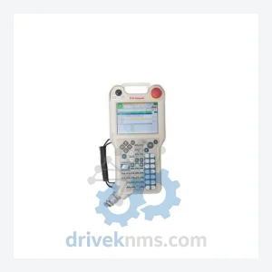
Kawasaki 50817-0066 Teach Pendant LCD Display Panel – Obsolete Robot Controller Spare Part
Kawasaki 50817-0066 is listed for PLC Modules RFQ review. Confirm quantity, condition and destination before quotation.
RFQ-ready industrial model
Model: 50999-2728 1QE-73 1QE-13 1QE-83
Product Overview
Commercial availability is handled through direct RFQ, model verification and export-oriented follow-up rather than public cart checkout.
Datasheet Preview
Use attached product manuals when available. If the manual is not public yet, request the full file directly through RFQ.
Commercial Path
Product pages on DRIVEKNMS are designed to verify model, brand and series first, then move the buyer into one clean quotation path.
Technical Dossier
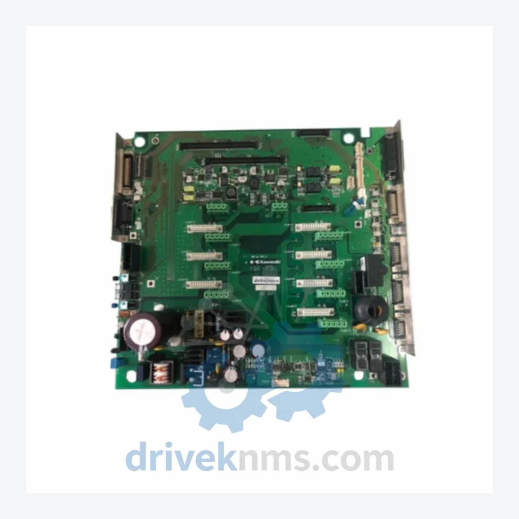
The Kawasaki 1QE Series represents a family of drive control and base board assemblies deployed across heavy industrial automation environments, including chemical processing plants, petroleum refineries, steel mills, and power generation facilities. These boards serve as the core signal processing and interface layer within Kawasaki robot controllers and industrial drive systems. Their long service life and wide installation base across Asia-Pacific and European heavy industry have made them a persistent demand item in the industrial spare parts market. The 50999-2728 base board, cross-referenced with sub-assemblies 1QE-73, 1QE-13, and 1QE-83, is a multi-function control board used in Kawasaki robot controller platforms, providing backplane communication, I/O interfacing, and drive signal routing functions.
The 1QE board family was developed as part of Kawasaki's modular robot controller architecture, designed to standardize the interface between servo drive amplifiers and the main CPU controller. Early variants in this lineage used discrete logic ICs and parallel bus communication, requiring precise backplane seating and periodic contact cleaning in high-vibration environments. Later revisions introduced surface-mount components and improved EMI shielding, addressing field failures observed in high-frequency switching environments common in arc welding and press-tending applications.
The following SKUs represent verified components within the Kawasaki 1QE and associated drive control board ecosystem. Each entry reflects a distinct functional role within the controller architecture:
50999-2728: Base board assembly; primary backplane interface for 1QE sub-modules
1QE-73: Drive signal routing sub-board; servo amplifier interface variant 73
1QE-13: I/O interface sub-board; digital signal conditioning variant 13
1QE-83: Control logic sub-board; drive enable and fault relay variant 83
50999-2101: CPU board; main processing unit for D-series Kawasaki controllers
50999-2102: Memory expansion board; program storage for robot teach data
50999-2103: Servo control board; multi-axis position command output
50999-2201: I/O base board; 32-channel digital I/O interface
50999-2202: Analog I/O board; 8-channel ±10V signal conditioning
50999-2301: Communication adapter board; RS-232/RS-422 serial interface
50999-2401: Power supply board; 24VDC regulated output for controller logic
50999-2501: Teach pendant interface board; operator panel signal routing
50999-2601: Safety relay board; dual-channel E-stop and safety gate monitoring
50999-2701: Fieldbus adapter board; DeviceNet/Profibus gateway module
50999-2728-A: Revised base board assembly; updated component revision of 50999-2728
1QE-03: Early-generation drive interface sub-board; predecessor to 1QE-13
1QE-43: Mid-generation servo signal board; intermediate revision between 1QE-13 and 1QE-73
1QE-93: Extended-channel drive board; 6-axis servo interface variant
The 1QE board family presents specific test challenges due to its role as a backplane communication and drive signal interface. DriveKNMS applies the following test protocol to all 1QE series boards prior to shipment:
Visual inspection: Component-level examination for burnt traces, failed capacitors, cracked solder joints, and connector pin damage — common failure modes in high-cycle robot controller environments.
Power-on functional test: Board is energized at rated voltage (24VDC logic rail) and monitored for correct power sequencing and absence of fault outputs.
Backplane communication test: Board is seated in a reference controller backplane and bus communication integrity is verified via loopback test.
Drive signal output test: Servo command signal outputs are measured against reference waveforms for amplitude, timing, and noise floor compliance.
Thermal soak: Board operates at elevated ambient temperature (50°C) for 2 hours to screen for latent thermal failures common in aged electrolytic capacitors.
Final documentation: Test results, board revision, and any replaced components are recorded and shipped with the unit.
Continue The Model Path
Move from this exact model into the matching system hub, brand archive, model-family archive or lifecycle sourcing route before sending a final RFQ list.
Related Paths
Kawasaki 50817-0066 is listed for PLC Modules RFQ review. Confirm quantity, condition and destination before quotation.
Kawasaki 50817-1371 is listed for Controller Cards RFQ review. Confirm quantity, condition and destination before quotation.
Kawasaki 50817-0128L05 is listed for HMI Panels RFQ review. Confirm quantity, condition and destination before quotation.