
KUKA KCP2 Teach Pendant Modules
KUKA KCP2 Series: Comprehensive Module Range and Technical Overview The KUKA KCP2 (KUKA Control Panel 2) teach pendant is the…
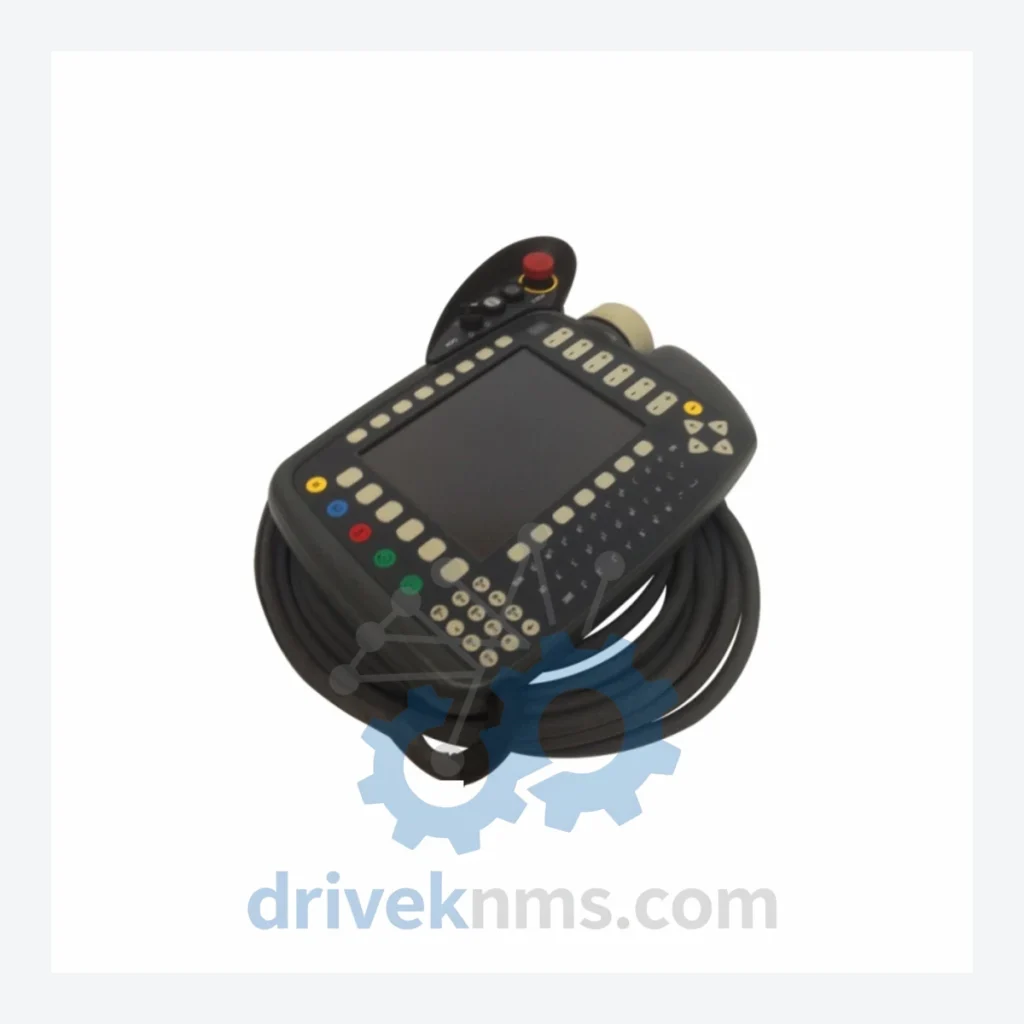
Model: 00-130-547 C2 KCP2
Product Overview
Commercial availability is handled through direct RFQ, model verification and export-oriented follow-up rather than public cart checkout.
Datasheet Preview
Use attached product manuals when available. If the manual is not public yet, request the full file directly through RFQ.
Commercial Path
Product pages on DRIVEKNMS are designed to verify model, brand and series first, then move the buyer into one clean quotation path.
Technical Dossier
The KUKA KCP2 (KUKA Control Panel 2) teach pendant is the primary human-machine interface for KUKA KR C2 robot controllers, deployed across heavy industrial sectors including automotive body-in-white assembly, chemical processing plants, nuclear facility maintenance robotics, and petroleum refinery automation. The KCP2 platform achieved widespread global installation from the late 1990s through the 2010s, making it one of the most extensively fielded teach pendants in industrial robotics history. Its ruggedized design, 6-axis jogging capability, and integrated safety enable circuit made it the reference standard for KUKA robot programming in high-hazard environments.
The KCP2 was introduced alongside the KR C2 controller platform (circa 1999) as a successor to the earlier KCP1 pendant used with KR C1 systems. The KCP2 introduced a color LCD display, improved ergonomics, and a dedicated enabling device (dead-man switch) compliant with EN 60204-1 safety standards. Early hardware revisions used a proprietary serial bus interface; later revisions transitioned to an Ethernet-based connection (KCP2 with RJ45) to support the KR C2 ed05 and KR C2 sr controller variants.
The KCP2 platform remained in active production until approximately 2013, when KUKA introduced the smartPAD (KCP4) for the KR C4 controller generation. The KCP2 is now classified as a mature/end-of-life product. Spare parts and refurbished units remain critical for facilities operating legacy KR C2 fleets, where controller replacement is cost-prohibitive. Long-term maintenance support for KCP2 is a primary service category at DriveKNMS.
Key architectural milestones: KCP2 Rev. A–C (serial bus, monochrome/early color LCD) → KCP2 Rev. D–F (color LCD, improved keypad membrane) → KCP2 C2 variant (enhanced cable assembly, updated connector housing) → KCP2 with Ethernet (RJ45 interface for ed05 controllers) → smartPAD / KCP4 (current generation, KR C4 only, not backward compatible).
The following SKUs represent verified, commonly sourced components within the KUKA KCP2 ecosystem. Each entry reflects a distinct hardware configuration or revision level.
00-130-547: KCP2 teach pendant, standard cable assembly, KR C2 compatible
00-130-547 C2: KCP2 teach pendant, C2 revision, updated connector and cable routing
00-168-894: KCP2 teach pendant with 10m cable, KR C2 / KR C2 ed05
00-168-895: KCP2 teach pendant with 15m cable extension, heavy-duty shielding
00-109-838: KCP2 enabling device (dead-man switch) assembly, replacement unit
00-109-839: KCP2 enabling device, 3-position safety switch, EN 60204-1 compliant
00-130-548: KCP2 display module, color LCD panel, direct replacement
00-130-549: KCP2 keypad membrane assembly, full key matrix replacement
00-130-550: KCP2 housing assembly, upper shell with integrated cable strain relief
00-130-551: KCP2 housing assembly, lower shell, battery compartment included
00-168-896: KCP2 cable assembly only, 10m, D-sub connector, KR C2 interface
00-168-897: KCP2 cable assembly only, 15m, shielded, for extended reach installations
00-130-552: KCP2 PCB main board, processor and display driver, core logic unit
00-130-553: KCP2 PCB interface board, keypad and enabling device signal conditioning
00-130-554: KCP2 battery pack, real-time clock backup, CR2032 compatible holder
00-168-898: KCP2 Ethernet variant, RJ45 interface, KR C2 ed05 / sr controllers
00-168-899: KCP2 Ethernet variant with 10m cable, ed05 controller series
00-130-555: KCP2 emergency stop button assembly, mushroom-head, IEC 60947-5-5
00-130-556: KCP2 mode selector switch, 3-position key switch, T1/T2/AUT/EXT modes
The KCP2 series reached end-of-production status, and OEM new-stock availability is effectively exhausted through standard distribution channels. DriveKNMS maintains a dedicated inventory of refurbished, tested, and new-old-stock KCP2 units and sub-components to support facilities with active KR C2 robot fleets. Our sourcing network covers decommissioned automotive and manufacturing lines across Europe, North America, and Asia, providing access to low-hour units that are otherwise unavailable through conventional supply chains.
For obsolete revision-specific variants (e.g., early Rev. A/B units required by older KR C2 controllers with firmware lock-in), DriveKNMS performs cross-revision compatibility assessment prior to shipment. All units are tested against the original KUKA functional specification before dispatch. Customers operating under long-term service agreements (LTSA) for chemical or nuclear facilities can request priority allocation and guaranteed lead times.
KCP2 units undergo a structured multi-stage inspection protocol at DriveKNMS. Stage 1: Visual inspection of housing, cable jacket, connector pins, and enabling device mechanism for mechanical wear or damage. Stage 2: Electrical continuity testing of all keypad matrix lines, emergency stop circuit, and enabling device switch contacts using calibrated test fixtures. Stage 3: Functional test on a live KR C2 controller bench — all operating modes (T1, T2, AUT, EXT) verified, display rendering confirmed, jogging axes 1–6 validated. Stage 4: Cable assembly insulation resistance test (500V DC Megger) to confirm shielding integrity, critical for installations in high-EMI environments such as welding cells and variable-frequency drive enclosures. Stage 5: Final firmware version check and documentation of hardware revision level for traceability.
Related Paths
KUKA KCP2 Series: Comprehensive Module Range and Technical Overview The KUKA KCP2 (KUKA Control Panel 2) teach pendant is the…
KUKA KCP2 VKCP2 Robot Control Panel: Sourcing Strategy & Asset Return Value in a Constrained Global Supply Chain The KUKA…
KUKA KSD1-08 Servo Drive: Procurement Strategy & Asset Return Value in a Constrained Supply Chain The KUKA KSD1-08 is a…