
KUKA KCP2 Teach Pendant Modules
KUKA KCP2 Series: Comprehensive Module Range and Technical Overview The KUKA KCP2 (KUKA Control Panel 2) teach pendant is the…
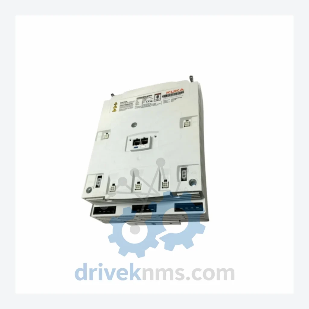
Model: 00-181-359KUKAZH 210/240
Product Overview
Commercial availability is handled through direct RFQ, model verification and export-oriented follow-up rather than public cart checkout.
Datasheet Preview
Use attached product manuals when available. If the manual is not public yet, request the full file directly through RFQ.
Commercial Path
Product pages on DRIVEKNMS are designed to verify model, brand and series first, then move the buyer into one clean quotation path.
Technical Dossier
The KUKA KR QUANTEC series represents one of the most widely deployed heavy-payload industrial robot platforms in global process industries. Installed across petrochemical refineries, nuclear facility material handling systems, automotive body-in-white lines, and offshore platform maintenance operations, the KR QUANTEC family covers payload capacities from 90 kg to 300 kg with reaches extending to 3,100 mm. The servo drive and motor subsystem — of which the KUKA 00-181-359 (KUKAZH 210/240) is a core axis drive component — is the primary maintenance expenditure category for operators running multi-shift production schedules. Axis motor failures account for the majority of unplanned downtime events in this platform, making verified spare parts availability a critical procurement requirement.
The KR QUANTEC platform was introduced by KUKA Roboter GmbH (Augsburg, Germany) as the successor to the KR 150/210/240/270 legacy series, consolidating multiple payload classes under a unified mechanical and electrical architecture. The controller pairing evolved from the KRC2 (introduced late 1990s) through the KRC4 (introduced 2010), with the KRC4 compact and KRC4 smallsize variants extending the platform into space-constrained installations.
The servo motor subsystem transitioned from resolver-based feedback (KRC2 era) to high-resolution absolute encoders (KRC4 era), introducing compatibility breaks that require careful part number verification during replacement. The 00-181-359 motor assembly is specific to the KUKAZH 210/240 axis configuration and is not interchangeable with earlier KR 210 L150-2 or KR 240-2 motor assemblies without controller parameter reconfiguration. Operators migrating from KRC2 to KRC4 controllers must verify motor feedback interface compatibility before substitution.
The following SKUs represent verified components within the KUKA KR QUANTEC and associated servo drive ecosystem. Each entry reflects a distinct functional role within the robot cell architecture.
00-181-359: A1/A2 axis servo motor assembly for KUKAZH 210/240; 3-phase AC synchronous, absolute encoder
00-181-358: A1 axis servo motor for KR QUANTEC 150/180 payload class; resolver feedback variant
00-181-360: A3 axis servo motor, KR QUANTEC 210/240; matched inertia for wrist-side load
00-130-442: KSD1-16 servo drive module, KRC4 cabinet; 16A continuous output current
00-130-443: KSD1-32 servo drive module, KRC4 cabinet; 32A continuous, high-payload axes
00-118-935: KPP 600-20 power supply module; 20A DC bus supply for KRC4 multi-axis cabinet
00-118-936: KPP 600-40 power supply module; 40A DC bus, extended multi-robot cell supply
00-160-552: RDC (Resolver/Encoder Digital Converter) board, KRC4; axis feedback signal processing
00-160-553: RDC board, KRC2 legacy; resolver-based feedback, discontinued production
00-168-894: CI3 communication interface board; EtherCAT fieldbus integration for KRC4
00-168-895: Profibus DP interface module, KRC4; legacy fieldbus compatibility adapter
00-185-388: A4/A5/A6 wrist axis motor assembly, KR QUANTEC; compact form factor, 3-phase AC
00-185-389: A6 axis motor, KR QUANTEC ultra variant; high-speed wrist rotation, 6000 RPM rated
00-109-483: KRC4 main computer board (PC unit); Intel-based, Windows Embedded runtime
00-109-484: Safety controller board (ESC), KRC4; dual-channel SIL2 certified safety monitoring
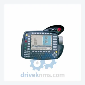
00-177-261: Teach pendant (smartPAD) cable assembly, 10m; KRC4 compatible, IP54 rated
00-177-262: smartPAD handheld teach pendant; 8.4-inch touchscreen, KRC4/KRC4 compact
The KR QUANTEC series entered its mature lifecycle phase with the introduction of the KR IONTEC and KR CYBERTECH series as KUKA's current-generation mid-payload platforms. While KUKA Roboter GmbH continues to support KRC4-based systems through its standard service agreement framework, component-level spare parts for earlier KRC2-paired QUANTEC installations are increasingly sourced through the secondary market.
DriveKNMS maintains a dedicated inventory program for KR QUANTEC lifecycle extension, covering the following supply scenarios: new-old-stock (NOS) components from original production runs; tested-and-certified refurbished assemblies with documented test reports; cross-reference sourcing for superseded part numbers where KUKA has issued replacement part designations. All 00-181-359 units processed by DriveKNMS are subject to axis load simulation testing prior to dispatch. Customers operating plants with 10+ year QUANTEC installations are advised to establish a consignment stock arrangement to reduce lead time exposure on critical axis motors.
Servo motor assemblies in the KR QUANTEC series require axis-specific validation due to the integrated absolute encoder calibration data stored in the motor's electronic nameplate (EMD). DriveKNMS applies the following test protocol to all 00-181-359 and related axis motor units:
Step 1 — Visual and mechanical inspection: Shaft runout measurement (<0.02 mm tolerance), bearing play assessment, connector pin integrity check (X20/X30 series Harting connectors).
Step 2 — Insulation resistance test: 500V DC Megger test across all phase windings to PE; minimum acceptance threshold 100 MΩ.
Step 3 — Encoder signal verification: Absolute encoder data readout via KUKA WorkVisual or equivalent diagnostic interface; confirmation of valid EMD data block.
Step 4 — No-load run test: Motor driven at rated speed (application-dependent, typically 2000–4000 RPM) for 30-minute thermal stabilization cycle; vibration signature recorded.
Step 5 — Load simulation: Resistive load bank applied to simulate rated torque; current draw and temperature rise logged against OEM specification envelope.
Units failing any single test stage are quarantined and not released for sale. Test records are available upon request for each serialized unit.
Related Paths
KUKA KCP2 Series: Comprehensive Module Range and Technical Overview The KUKA KCP2 (KUKA Control Panel 2) teach pendant is the…
KUKA KCP2 VKCP2 Robot Control Panel: Sourcing Strategy & Asset Return Value in a Constrained Global Supply Chain The KUKA…
KUKA KSD1-08 Servo Drive: Procurement Strategy & Asset Return Value in a Constrained Supply Chain The KUKA KSD1-08 is a…