
KUKA KCP2 Teach Pendant Modules
KUKA KCP2 Series: Comprehensive Module Range and Technical Overview The KUKA KCP2 (KUKA Control Panel 2) teach pendant is the…
Model: 00-192-295 00-192-296 00-118-966 C2
Product Overview
Commercial availability is handled through direct RFQ, model verification and export-oriented follow-up rather than public cart checkout.
Datasheet Preview
Use attached product manuals when available. If the manual is not public yet, request the full file directly through RFQ.
Commercial Path
Product pages on DRIVEKNMS are designed to verify model, brand and series first, then move the buyer into one clean quotation path.
Technical Dossier
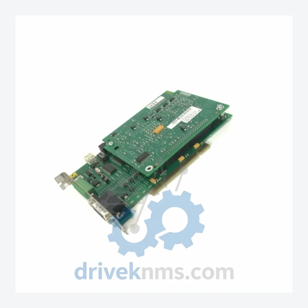
The KUKA C2 controller platform represents a pivotal generation in KUKA Roboter GmbH's industrial robot control architecture, deployed extensively across heavy-industry sectors including automotive body-in-white assembly, chemical plant material handling, nuclear facility maintenance robotics, and refinery process automation. The C2 cabinet controller succeeded the C1 generation and preceded the KRC1/KRC2 transition, occupying a critical installed base in facilities where robot replacement is cost-prohibitive. The Interbus fiber optic communication cards — specifically part numbers 00-192-295, 00-192-296, and 00-118-966 — are the primary fieldbus interface modules enabling the C2 controller to communicate with peripheral I/O nodes, conveyor systems, and safety PLCs via the Interbus-S (IBS) protocol over plastic or glass fiber optic cabling. These modules are no longer in active production, making verified surplus stock the only viable sourcing channel for maintenance operations.
KUKA's controller architecture evolved through distinct generations: the C1 (early 1980s, relay-logic based), C2 (mid-1980s to mid-1990s, PC-based with proprietary backplane), KRC1 (late 1990s, Windows NT/VME hybrid), KRC2 (2000–2010, standardized PC architecture), and the current KRC4/KRC5 platform. The C2 generation introduced a modular backplane design with dedicated slots for CPU, I/O, and fieldbus communication cards. Interbus-S was selected as the primary fieldbus due to its deterministic ring topology and suitability for time-critical robot peripheral communication. The fiber optic variant of the Interbus interface (as opposed to copper RS-485) was mandated in environments with high electromagnetic interference — common in welding cells and high-voltage switchgear areas. Compatibility between C2 Interbus cards and later KRC1 systems is not supported at the hardware level; the backplane bus architecture, slot pitch, and firmware handshake protocols are incompatible. Facilities running C2 controllers must source C2-specific spare parts exclusively.
The following part numbers are documented within the KUKA C2 controller spare parts ecosystem. Each entry reflects a distinct hardware revision or functional variant within the Interbus fiber optic communication subsystem.
Interbus / Fiber Optic Communication Cards
The KUKA C2 controller series reached end-of-production in the mid-1990s and entered full end-of-support status by the early 2000s. KUKA Roboter GmbH no longer manufactures, repairs, or provides firmware updates for C2-generation hardware. For facilities operating C2 robots under long-term maintenance contracts — particularly in automotive stamping plants, foundries, and process industries where robot replacement requires extensive re-engineering — DriveKNMS maintains a dedicated inventory of tested C2 spare parts sourced from decommissioned systems, authorized surplus channels, and controlled-environment storage. Part numbers 00-192-295, 00-192-296, and 00-118-966 are stocked subject to availability and are dispatched with full functional test documentation. DriveKNMS provides lifecycle extension support including cross-reference identification for unmarked boards, firmware version verification, and compatibility confirmation against specific C2 cabinet serial number ranges.
KUKA C2 Interbus fiber optic cards present specific test challenges due to their proprietary backplane bus protocol and the absence of modern diagnostic software support. DriveKNMS applies the following verification procedures to all C2 Interbus modules prior to dispatch: (1) Visual inspection for capacitor degradation, PCB trace corrosion, and connector pin integrity — common failure modes in boards stored beyond 15 years. (2) Backplane bus signal integrity test using a C2-compatible test rig to verify address decoding, interrupt lines, and data bus handshake. (3) Fiber optic transceiver power output measurement (850nm wavelength, plastic fiber standard) to confirm transmitter LED output within specification. (4) Interbus ring initialization test: the card is installed in a live C2 test cabinet and a minimum 4-node Interbus ring is established to confirm master controller functionality, remote bus coupler recognition, and cyclic data exchange. (5) Firmware revision logging: the firmware version is recorded and cross-referenced against known-compatible C2 software releases to prevent version mismatch on installation. All units are shipped with an individual test report referencing the specific part number, serial number, and test date.
For sourcing inquiries, cross-reference requests, or bulk spare parts orders for KUKA C2 Interbus fiber optic modules:
Related Paths
KUKA KCP2 Series: Comprehensive Module Range and Technical Overview The KUKA KCP2 (KUKA Control Panel 2) teach pendant is the…
KUKA KCP2 VKCP2 Robot Control Panel: Sourcing Strategy & Asset Return Value in a Constrained Global Supply Chain The KUKA…
KUKA KSD1-08 Servo Drive: Procurement Strategy & Asset Return Value in a Constrained Supply Chain The KUKA KSD1-08 is a…