
KUKA KCP2 Teach Pendant Modules
KUKA KCP2 Series: Comprehensive Module Range and Technical Overview The KUKA KCP2 (KUKA Control Panel 2) teach pendant is the…
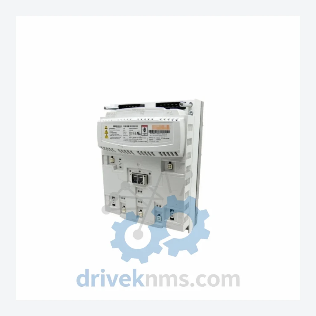
Model: 00-245-213 KSP 600-3X20
Product Overview
Commercial availability is handled through direct RFQ, model verification and export-oriented follow-up rather than public cart checkout.
Datasheet Preview
Use attached product manuals when available. If the manual is not public yet, request the full file directly through RFQ.
Commercial Path
Product pages on DRIVEKNMS are designed to verify model, brand and series first, then move the buyer into one clean quotation path.
Technical Dossier
The KUKA KSP 600 (Kompakt-Servo-Pack 600) series represents one of the most widely deployed servo drive platforms in global heavy industry. Installed across chemical processing plants, nuclear facility material handling systems, automotive body-in-white lines, and petroleum refinery automation infrastructure, the KSP 600 family provides axis-level servo power conversion and control within KUKA's KR C2 and KR C4 robot controller ecosystems. Its compact multi-axis architecture — delivering up to 3×20A continuous output per module — made it the standard drive solution for KUKA's KR 6, KR 16, KR 30, KR 60, and KR 100 robot families throughout the 2000s and 2010s. The series remains in active service at thousands of industrial sites globally, making reliable spare parts sourcing a critical operational requirement for maintenance engineers and plant managers.
The KSP 600 series was introduced as part of KUKA's transition from the earlier KSD (KUKA Servo Drive) discrete drive architecture to an integrated, compact multi-axis servo pack format. Early KR C2 controllers (circa 2000–2004) used single-axis KSD drives; the KSP 600 consolidated multiple axes into a single backplane-mounted module, reducing cabinet footprint and simplifying cabling.
The core KSP 600 architecture uses a DC bus intermediate circuit fed from the KPS (KUKA Power Supply) module, distributing 600V DC across all connected KSP units. Each KSP module contains independent IGBT inverter stages per axis, with axis-level current control loops running at high switching frequencies. Communication with the KR C2 or KR C4 controller CPU is handled via the internal DSE (Drive System Electronics) bus or, in later revisions, via EtherCAT-based KSB (KUKA System Bus) interfaces.
Compatibility considerations are significant for maintenance teams: KSP 600 modules are firmware-dependent and must match the KR C controller software version. Cross-generation substitution between KR C2 and KR C4 variants requires hardware and firmware validation. Later production runs introduced revised IGBT modules and updated gate driver boards, which are not always backward-compatible with early-revision backplanes. DriveKNMS maintains revision-level records for all KSP 600 stock to ensure compatibility matching prior to shipment.
The following SKUs represent the primary module variants within the KUKA KSP 600 series, organized by axis count and current rating. All models listed are confirmed production units within the KSP 600 platform.
00-245-213 KSP 600-3X20: 3-axis servo pack, 3×20A continuous, KR C2/C4 compatible, standard robot axes 1–3 or 4–6 configuration.
00-130-442 KSP 600-3X20: Alternate part number variant of the 3×20A triple-axis pack; used in mid-series KR C2 builds.
00-245-214 KSP 600-3X40: 3-axis servo pack, 3×40A continuous; deployed on higher-payload KR 60 and KR 100 robot variants.
00-245-215 KSP 600-3X64: 3-axis servo pack, 3×64A continuous; used on heavy-duty KR 150 and KR 210 configurations.
00-245-216 KSP 600-1X40: Single-axis servo pack, 1×40A; typically assigned to external axis (E1) or positioner drive applications.
00-245-217 KSP 600-1X64: Single-axis servo pack, 1×64A; high-current external axis or heavy positioner drive.
00-245-218 KSP 600-2X20: Dual-axis servo pack, 2×20A; used in compact 5-axis or 6-axis configurations with mixed module sets.
00-245-219 KSP 600-2X40: Dual-axis servo pack, 2×40A; mid-payload dual-axis applications.
00-130-443 KSP 600-3X20 (Revised): Updated gate driver revision; introduced improved thermal management over the 00-245-213 baseline.
00-130-444 KSP 600-3X40 (Revised): Revised 3×40A variant with updated IGBT module generation.
00-245-220 KSP 600-3X20 KR C4: KR C4-specific variant; EtherCAT-based KSB communication interface, not compatible with KR C2 backplanes.
00-245-221 KSP 600-3X40 KR C4: KR C4 3×40A variant; updated firmware interface for KR C4 software stack.
00-245-222 KSP 600-1X20: Single-axis, 1×20A; low-payload external axis or auxiliary drive applications.
00-245-223 KSP 600-3X20 (Low Voltage): Variant configured for 480V AC input markets; same mechanical form factor as standard 600V DC bus units.
00-245-224 KSP 600-3X64 KR C4: KR C4 heavy-duty 3×64A variant; used on KR 210 and KR 270 ultra-heavy payload robots.
00-245-225 KSP 600-2X64: Dual-axis, 2×64A; specialized configuration for high-torque positioner or external axis pairs.
The KSP 600 series has entered the mature-to-declining phase of its product lifecycle. KUKA's official spare parts support for KR C2-generation hardware has been progressively reduced, with new production of certain KSP 600 variants discontinued. For plant operators running KR C2-based robot fleets — common in automotive stamping, foundry, and chemical processing environments — this creates a structural supply risk for unplanned maintenance events.
DriveKNMS maintains a dedicated inventory of KSP 600 modules sourced from decommissioned robot cells, authorized surplus channels, and controlled refurbishment programs. Our procurement team actively tracks KSP 600 availability across global industrial surplus markets, enabling us to fulfill both single-unit emergency replacement orders and multi-unit planned maintenance contracts. For obsolete or low-volume variants such as the KSP 600-2X64 or KSP 600-1X20, lead times and availability are confirmed at the time of inquiry. Customers are encouraged to submit full BOM (Bill of Materials) lists for fleet-level maintenance planning to receive consolidated availability and pricing.
The KSP 600 module architecture presents specific test challenges due to its integrated multi-axis inverter design and DC bus dependency. DriveKNMS applies a structured test protocol to all KSP 600 units prior to shipment:
DC bus integrity verification is performed at rated voltage (600V DC) to confirm bus capacitor condition and pre-charge circuit function. Each IGBT inverter stage is individually tested under load using a calibrated motor simulator, verifying gate drive signals, switching waveforms, and current regulation accuracy per axis. The DSE or EtherCAT communication interface is validated against a reference KR C2 or KR C4 controller to confirm firmware handshake and axis enable sequences. Thermal imaging is applied during load testing to identify hot spots indicative of degraded IGBT modules or failing gate resistors. Final functional verification includes a full axis enable/disable cycle and fault code readback via the controller interface. Units that do not pass all stages are either repaired to component level or quarantined from inventory.
© 2026 DriveKNMS. All trademarks belong to their respective owners. Specifications are for reference only and subject to change without notice. Verify all parameters against official documentation before installation.
Related Paths
KUKA KCP2 Series: Comprehensive Module Range and Technical Overview The KUKA KCP2 (KUKA Control Panel 2) teach pendant is the…
KUKA KCP2 VKCP2 Robot Control Panel: Sourcing Strategy & Asset Return Value in a Constrained Global Supply Chain The KUKA…
KUKA KSD1-08 Servo Drive: Procurement Strategy & Asset Return Value in a Constrained Supply Chain The KUKA KSD1-08 is a…