
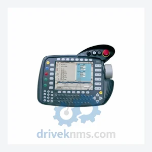
KUKA KCP2 Teach Pendant Modules
KUKA KCP2 Series: Comprehensive Module Range and Technical Overview The KUKA KCP2 (KUKA Control Panel 2) teach pendant is the…
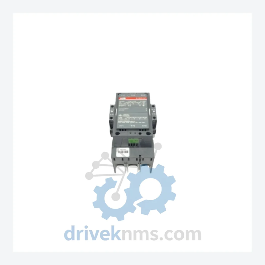
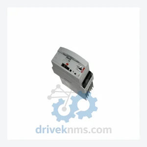
Model: KSD1-48C200-105-413
Product Overview
Commercial availability is handled through direct RFQ, model verification and export-oriented follow-up rather than public cart checkout.
Datasheet Preview
Use attached product manuals when available. If the manual is not public yet, request the full file directly through RFQ.
Commercial Path
Product pages on DRIVEKNMS are designed to verify model, brand and series first, then move the buyer into one clean quotation path.
Technical Dossier
The KUKA KSD1 series represents the primary servo drive platform deployed across KUKA robot controllers, most notably the KRC2 and KRC3 cabinet generations. These drives are installed in high-density industrial environments including automotive body-in-white assembly lines, chemical processing facilities, nuclear material handling systems, and petroleum refinery automation cells. The KSD1 platform operates as an axis-specific servo amplifier, receiving motion commands from the KRC controller's DSE (Digital Servo Electronics) board and delivering regulated three-phase power output to KUKA synchronous servo motors. Each KSD1 unit is rated for a specific continuous and peak current envelope, identified by the numeric suffix in the part number (e.g., C48, C64, C200). Global installed base of KRC2-based systems ensures sustained demand for KSD1 modules well into the 2030s, as full controller replacement cycles in heavy industry typically span 15–20 years.
The KSD1 series was introduced alongside the KRC2 controller platform in the late 1990s as a replacement for the earlier KSD (non-suffixed) drives used in KRC1 cabinets. The KSD1 architecture introduced a standardized 48V DC bus interface, improved thermal management via integrated heat sink fins, and a unified connector layout compatible with the KRC2 backplane. Early KSD1 variants (pre-2003) used discrete IGBT modules; later revisions transitioned to integrated power modules with improved short-circuit protection. The KSD1 series is mechanically and electrically incompatible with the subsequent KSD2 and KSP series introduced with the KRC4 platform (post-2010). This incompatibility creates a hard boundary: KRC2 systems cannot accept KSD2/KSP drives without full cabinet replacement. As a result, KSD1 modules are classified as lifecycle-critical spare parts for any facility operating KRC2-generation robots. KUKA officially discontinued new production of most KSD1 variants, making secondary-market sourcing the primary procurement channel for maintenance operations.
The following SKUs represent verified, commonly referenced KSD1 series part numbers. Each unit functions as an axis servo amplifier within the KRC2 drive cabinet. Current ratings and axis assignments vary by suffix.
DriveKNMS maintains a dedicated inventory program for end-of-life KUKA KSD1 series components. As KUKA has ceased new production of KSD1 variants, procurement through the OEM channel is no longer viable for most part numbers. DriveKNMS sources KSD1 modules through verified industrial surplus channels, decommissioned robot cell buybacks, and authorized refurbishment pipelines. All units are catalogued by part number suffix (-000, -300, -413, -413-S) to ensure hardware revision accuracy. Cross-revision compatibility is assessed on a case-by-case basis, as firmware dependencies within the KRC2 DSE board may restrict interchangeability between early and late hardware revisions. Customers operating multi-robot facilities are advised to maintain a minimum buffer stock of KSD1 drives matched to their installed axis current ratings. DriveKNMS provides revision-matched replacement recommendations upon receipt of the customer's existing drive label data.
Each KSD1 unit processed by DriveKNMS undergoes a structured verification protocol designed around the specific electrical architecture of the KRC2 servo drive bus. Testing stages include: (1) DC bus capacitor ESR measurement and capacitance verification against OEM specification; (2) IGBT gate drive signal integrity check under simulated load conditions; (3) current feedback loop calibration verification using a resistive load bank matched to the drive's rated current class; (4) thermal cycling test to confirm heat sink contact integrity and thermal interface material condition; (5) backplane connector pin inspection for fretting corrosion, a known failure mode in KSD1 units subjected to vibration-heavy environments; (6) firmware version identification and logging for KRC2 compatibility cross-reference. Units that fail any stage are quarantined and not offered for resale. Test records are retained per unit and available upon request for quality-critical procurement processes.
Related Paths
KUKA KCP2 Series: Comprehensive Module Range and Technical Overview The KUKA KCP2 (KUKA Control Panel 2) teach pendant is the…
KUKA KCP2 VKCP2 Robot Control Panel: Sourcing Strategy & Asset Return Value in a Constrained Global Supply Chain The KUKA…
KUKA KSD1-08 Servo Drive: Procurement Strategy & Asset Return Value in a Constrained Supply Chain The KUKA KSD1-08 is a…