
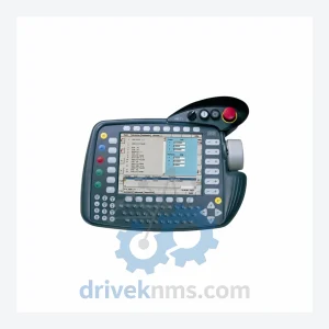
KUKA KCP2 Teach Pendant Modules
KUKA KCP2 Series: Comprehensive Module Range and Technical Overview The KUKA KCP2 (KUKA Control Panel 2) teach pendant is the…
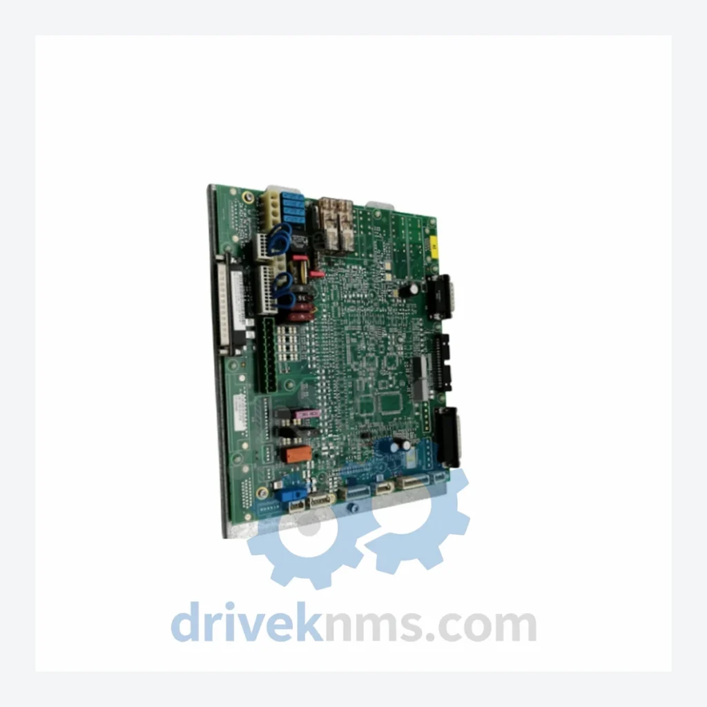
Model: MFC+DSE 00-117-336 00-128-358 033.59.20.99G PClF
Product Overview
Commercial availability is handled through direct RFQ, model verification and export-oriented follow-up rather than public cart checkout.
Datasheet Preview
Use attached product manuals when available. If the manual is not public yet, request the full file directly through RFQ.
Commercial Path
Product pages on DRIVEKNMS are designed to verify model, brand and series first, then move the buyer into one clean quotation path.
Technical Dossier
The KUKA MFC+DSE (Motion and Function Controller + Drive System Electronics) series represents a core hardware platform deployed across KUKA KRC2 and KRC4 robot controller generations. These modules are installed in high-cycle industrial environments including automotive body-in-white assembly, heavy-load palletizing, arc welding cells, and precision material handling in chemical processing plants, nuclear facility maintenance robots, and refinery automation lines. The MFC+DSE architecture integrates motion interpolation, axis coordination, and drive-level feedback into a compact backplane-mounted module set, making it a critical component in any KUKA robot controller maintenance or refurbishment program.
The MFC+DSE lineage originates from KUKA's transition away from discrete motion control boards in the early KRC1 era toward integrated DSP-based motion controllers in the KRC2 platform (introduced circa 1999). The original MFC (Motion Function Controller) handled trajectory planning and axis interpolation, while the DSE (Drive System Electronics) managed servo amplifier communication via the KUKA proprietary SESC bus. In the KRC2 ed05 and ed05 2010 revisions, the MFC+DSE was consolidated into a single board assembly, reducing backplane slot count and improving signal integrity. The KRC4 generation (post-2010) migrated to the KPP (KUKA Power Pack) and KSP (KUKA Servo Pack) architecture, rendering the MFC+DSE series a legacy platform. However, given the installed base of KRC2 controllers still operating in production environments globally, the MFC+DSE remains in active demand for spare parts and lifecycle extension programs. Compatibility is strictly limited to KRC2 variants; cross-generation substitution with KRC4 hardware is not supported.
The following SKUs represent verified components within the KUKA MFC+DSE and associated KRC2 controller module ecosystem. Each entry reflects a distinct functional role within the controller backplane:
MFC+DSE 00-117-336 00-128-358 033.59.20.99G PClF: Combined motion/drive controller board, KRC2 ed05, PCI-format backplane interface.
MFC2 00-109-575: Motion Function Controller 2nd generation, KRC2 standard, 6-axis interpolation support.
MFC3 00-130-623: Motion Function Controller 3rd generation, enhanced DSP, KRC2 ed05 2010 compatible.
DSE 00-106-270: Drive System Electronics board, SESC bus master, KRC2 base variant.
DSE 00-117-337: Drive System Electronics, revised firmware ROM, KRC2 ed05 variant.
DSE-IBS 00-109-576: DSE with integrated INTERBUS-S fieldbus interface for external I/O expansion.
MFC-IBS 00-109-577: MFC with INTERBUS-S master port, used in distributed I/O topologies.
KPS-27/20 00-116-342: KUKA Power Supply 27V/20A, primary backplane power for KRC2 MFC+DSE systems.
KPS-600/20 00-118-860: High-capacity power supply, 600V DC bus, servo drive support module.
CI3 00-109-578: Customer Interface board, 24V digital I/O, KRC2 backplane slot, 16DI/16DO.
CI4 00-130-624: Customer Interface 4th generation, expanded I/O, EtherCAT-ready variant.
SIB 00-117-338: Safety Interface Board, KRC2 ESC safety circuit integration, category 3 stop.
SIB-Extended 00-130-625: Extended Safety Interface Board, dual-channel monitoring, KRC4 transition-compatible.
RDC 00-109-579: Resolver-to-Digital Converter board, 6-axis resolver signal conditioning, KRC2.
RDC3 00-130-626: RDC 3rd generation, 8-axis support, improved noise immunity, KRC2 ed05 2010.
KVGA 00-109-580: KUKA VGA display controller, KRC2 teach pendant interface board.
PMB 00-117-339: Power Management Board, battery-backed SRAM and real-time clock for KRC2.
CCU 00-130-627: Cabinet Control Unit, KRC4 migration bridge module, limited KRC2 ed05 2010 compatibility.
The KUKA MFC+DSE series entered end-of-production status as KUKA phased out KRC2 controller manufacturing. Official KUKA spare parts availability through authorized channels is limited and subject to extended lead times or permanent discontinuation notices. DriveKNMS maintains a dedicated inventory of tested MFC+DSE modules sourced through certified industrial surplus channels, decommissioned robot cell buybacks, and OEM overstock programs. For end-users operating KRC2 fleets beyond the standard 10-year support window, DriveKNMS provides lifecycle extension services including board-level repair, firmware restoration to factory revision, and functional equivalency testing. Customers requiring long-term maintenance agreements for multi-unit KRC2 installations are encouraged to contact DriveKNMS for volume pricing and consignment stocking arrangements.
MFC+DSE modules present specific test challenges due to their integrated backplane bus architecture and DSP-dependent firmware execution. DriveKNMS applies the following verification protocol to all MFC+DSE units prior to dispatch: (1) Visual inspection for capacitor ESR degradation, SESC bus connector pin integrity, and PCB trace corrosion common in high-humidity environments. (2) Powered bench test using a KRC2 test rig with known-good companion boards to verify SESC bus enumeration and axis interpolation handshake. (3) Firmware version verification against KUKA revision matrix to confirm compatibility with target KRC2 software version (V4.1 through V5.6). (4) 48-hour burn-in cycle under simulated axis load to screen for latent thermal failures. (5) Final functional test with motion program execution across all 6 axes to confirm interpolation accuracy within KUKA specification. All units ship with a test report and 12-month warranty against functional defect.
Related Paths
KUKA KCP2 Series: Comprehensive Module Range and Technical Overview The KUKA KCP2 (KUKA Control Panel 2) teach pendant is the…
KUKA KCP2 VKCP2 Robot Control Panel: Sourcing Strategy & Asset Return Value in a Constrained Global Supply Chain The KUKA…
KUKA KVGA Series: Comprehensive Module Range and Technical Overview The KUKA KVGA (KRC Video Graphics Adapter) series is a family…